Pulse output instructions
1041
Part III FP Instructions
option in your positioning program.
The status of the high-speed counter control flag or pulse output control flag may
change while a scan is being carried out. For example, if the flag is used more
than once as an input condition, different statuses may exist within one scan. To
ensure proper execution of the program, the status of the special internal relay
should be copied to a variable at the beginning of the program.
Running the FP0R in FP0 compatibility mode
To run the FP0R in FP0 compatibility mode, you can download an FP0 program to the FP0R.
Please note the following restrictions:
The FP0R supports signed 32-bit data for elapsed value and target value; the
FP0 supports signed 24-bit data. In FP0 compatibility mode, counting and pulse
output continue even if data exceeds the FP0 range.
The duty ratio is always 25% regardless of the settings in the instructions. With
the pulse output method "pulse/direction", pulses are output approx. 300s after
the direction signal has been output; the motor driver characteristics are
simultaneously taken into consideration.
The FP0R does not support the "no counting" setting. Instead, incremental
counting is performed with the FP0 pulse output instructions set to "no counting".
The maximum pulse output frequency is 10000Hz.
Make sure the pulse output instruction does not use an output that is also being
used as a normal output.
For an FP0 program to be able to run in FP0 compatibility mode, the PLC types
(C10, C14, C16, C32, and T32) must match exactly. FP0 compatibility mode is
not available for the F32 type FP0R.
PLC types Availability of F169_PulseOutput_Jog (see page 1322)
Variable Data type Function
s_dutDataTable F169_PulseOutput_Jog_DUT Starting address of area containing the data table
n_iPulseOutputChannel INT Pulse output: 0 or 1
For Relay T/C Register Constant
s_dutDataTable - - - - - - DT - - -
n_iPulseOutputChannel - - - - - - - - - dec. or hex.
No. IEC address Set If
R9007 %MX0.900.7 permanently
R9008 %MX0.900.8 for an instant
channel number or values of the data table are
outside the permissible range
Data types
Operands
Error flags
Example
In this example the function has been programmed in ladder diagram (LD) and structured text (ST).
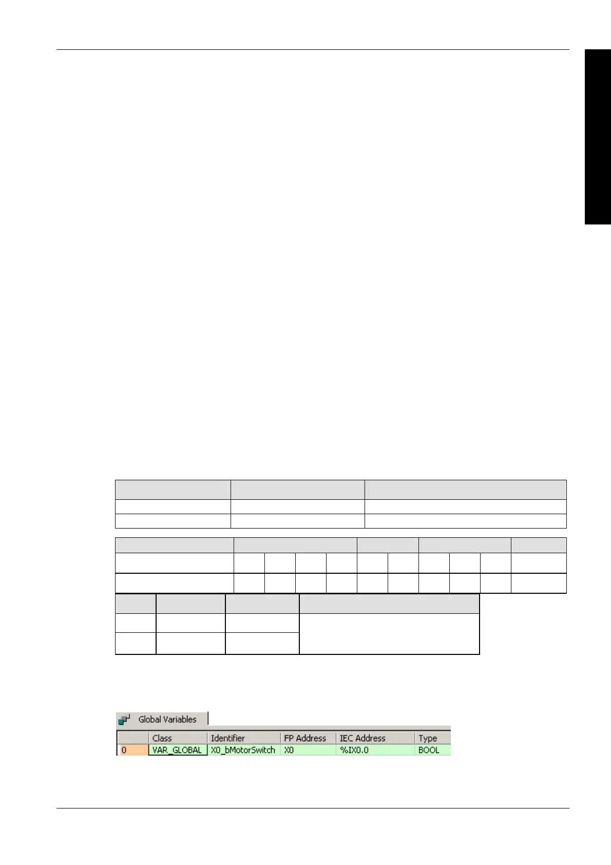
GVL
In the global variable list you define variables that can be accessed by all POUs in the project.
DUT

 Loading...


