Pulse output instructions
1044
Part III FP Instructions
To run the FP0R in FP0 compatibility mode, you can download an FP0 program to the FP0R.
PLC types Availability of F170_PulseOutput_PWM (see page 1322)
Variable Data type Function
s_dutDataTable F170_PulseOutput_PWM_DUT Starting address of area containing the data table
n_iPulseOutputChannel INT Pulse output channel:: 0 or 1
For Relay T/C Register Constant
s_dutDataTable - - - - - - DT - - -
n_iPulseOutputChannel - - - - - - - - - dec. or hex.
No. IEC address Set If
R9007 %MX0.900.7 permanently
R9008 %MX0.900.8 for an instant
channel number or values of the data table are outside the
permissible range
Data types
Operands
Error flags
Example
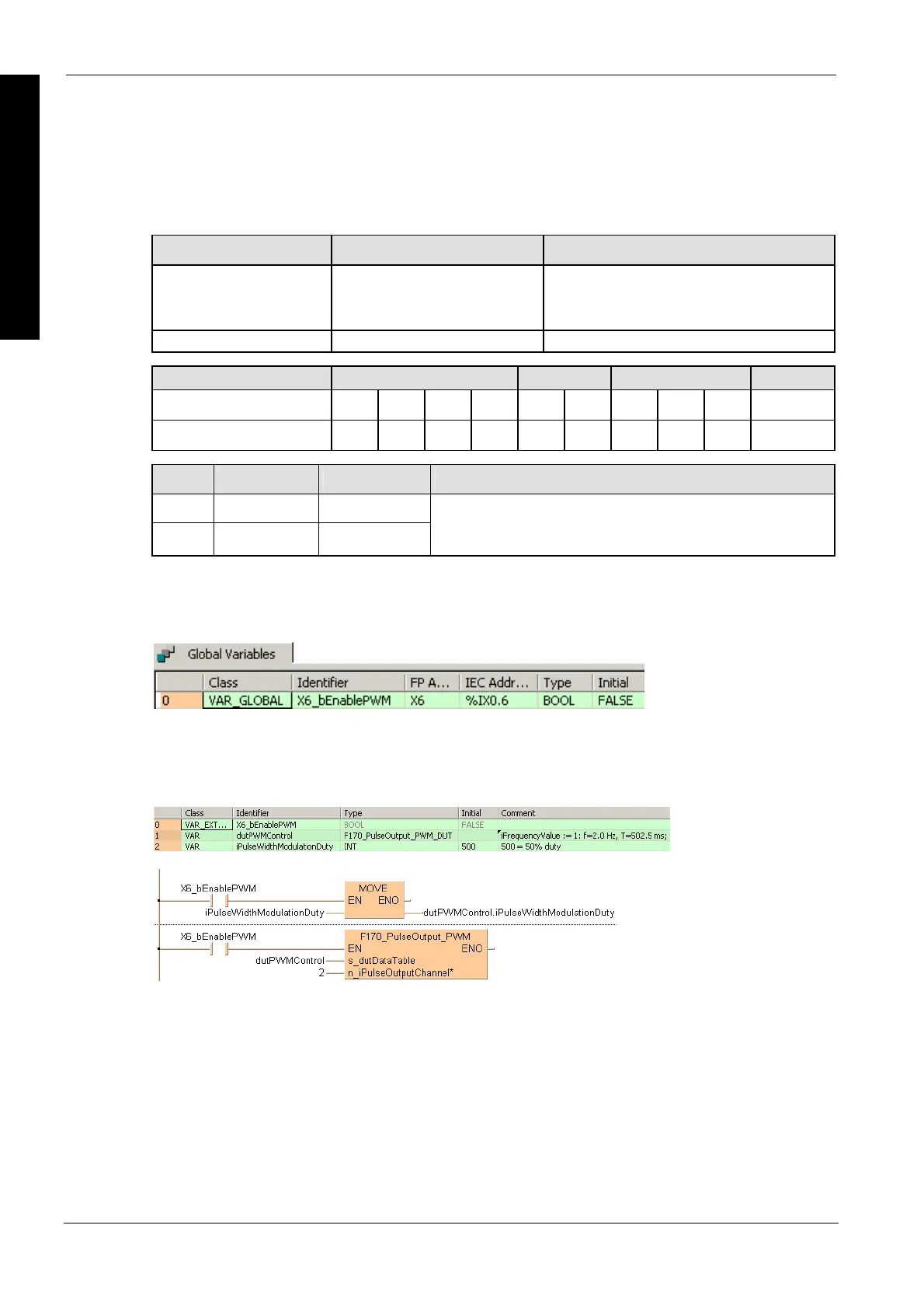
In this example the function has been programmed in ladder diagram (LD) and structured text (ST).
GVL
In the global variable list, you define variables that can be accessed by all POUs in the project.
DUT
The DUT F170_PulseOutput_PWM_DUT is predefined in the FP Library.
POU header
All input and output variables used for programming this function have been declared in the POU
header.
LD
ST

 Loading...


