Pulse output instructions
1043
Part III FP Instructions
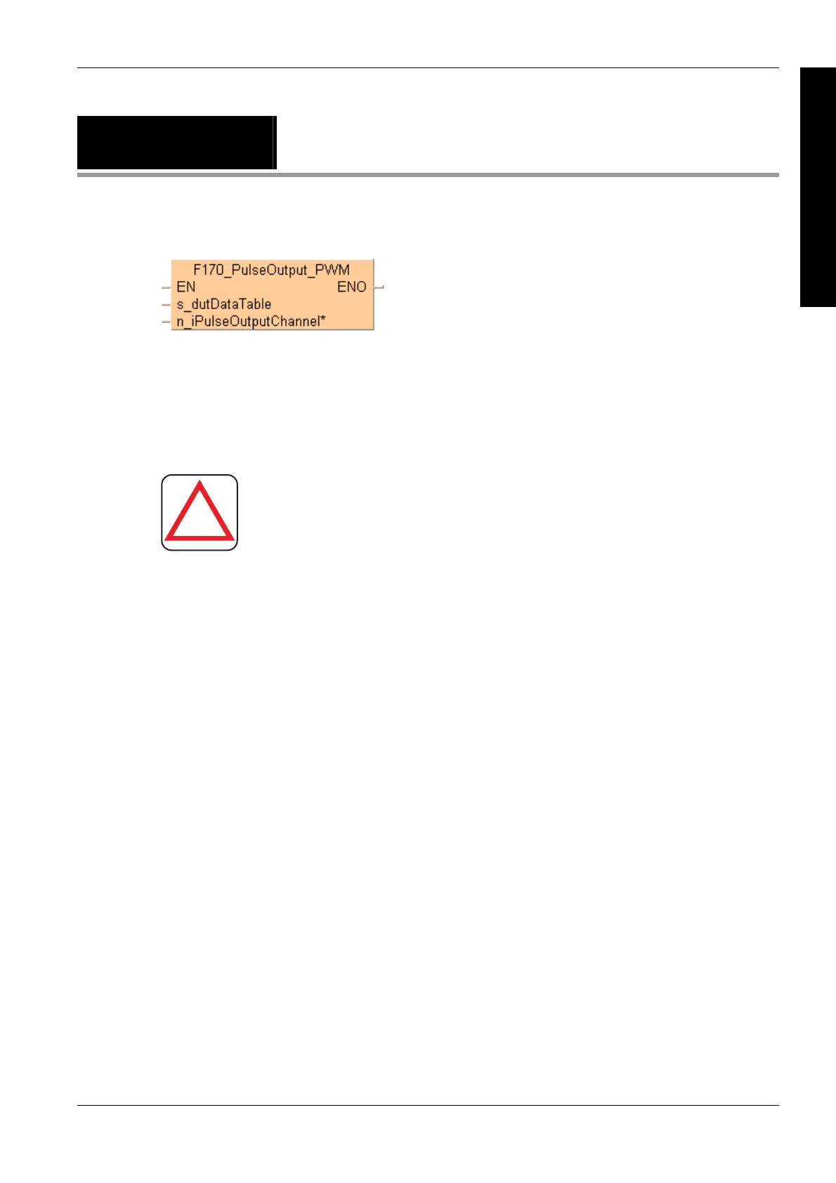
F170_PulseOutput_
PWM
PWM output
Use the following predefined DUT: F170_PulseOutput_PWM_DUT
The following parameters can be specified in the DUT:
Approximate frequency
Duty ratio (for pulse duration and period)
General programming information
!
Warning!
As soon as you begin editing a program online (i.e., in
RUN mode) using this instruction, pulse output will
stop.
Set any high-speed counter allocated to a pulse output channel to "Unused" in
the system registers.
If both the main program and the interrupt program contain code for the same
channel, make sure both are not executed simultaneously.
The high-speed counter control flag (e.g. sys_bIsHscChannel0ControlActive) and
the pulse output control flag (e.g. sys_bIsPulseChannel0Active) are assigned to
the same internal relay (e.g. R903A). Therefore, when a high-speed counter
instruction or a pulse output instruction is executed, both the high-speed counter
control flag (e.g. sys_bIsHscChannel0ControlActive) and the pulse output control
flag (e.g. sys_bIsPulseChannel0Active) for the channel used are TRUE. No other
high-speed counter instruction or pulse output instruction can be executed as
long as this flag is TRUE.
At a point close to the minimum or maximum duty ratio, the output is delayed,
which may cause the duty ratio to differ from the specified value.
The duty ratio can be changed for each scan. The change becomes effective
with the next pulse output. The frequency setting is only effective at the start of
execution of an instruction.
We strongly recommend that you incorporate a forced stop (see page 1021)
option in you
r positioning p
rogram.
The status of the high-speed counter control flag or pulse output control flag may
change while a scan is being carried out. For example, if the flag is used more
than once as an input condition, different statuses may exist within one scan. To
ensure proper execution of the program, the status of the special internal relay
should be copied to a variable at the beginning of the program.
Using the FP0 compatibility mode of the FP0R
Description
This instruction delivers a pulse width modulated output signal according to the specified DUT.
Pulses are output from the specified channel when the control flag for this channel is FALSE and
the execution condition is TRUE.

 Loading...


