Appendix Programming Information
1284
Hold on/off
No
.
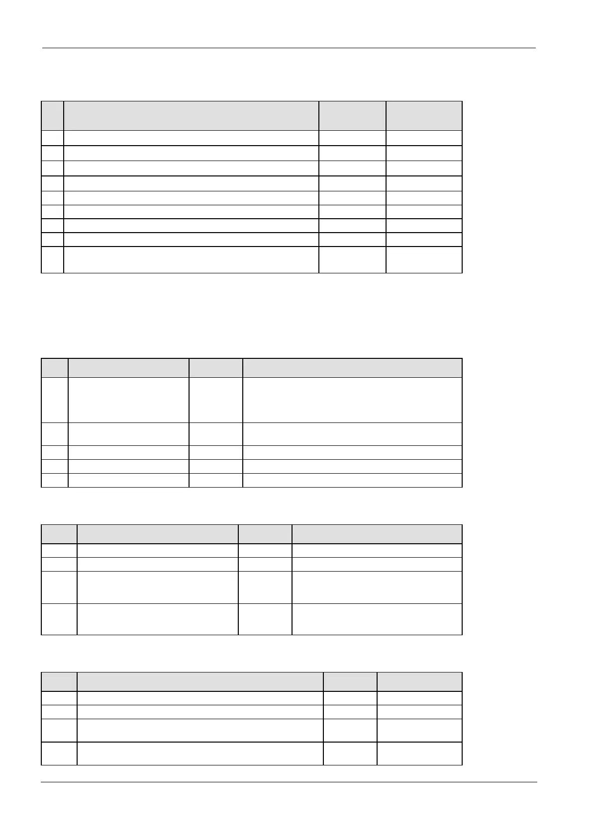
Name Default Values
5
1)
Counter start address 1008 0–1024
6
1)
Timer/Counter hold area start address 1008 0–1024
7
1)
Internal relay hold area start address (in word units) 248 0–256
8
1)
Data register hold area start address 32710 0–32763
10 Link relay hold area start address for PLC Link 0 (in word units) 64 0–64
11 Link relay hold area start address for PLC Link 1 (in word units) 128 64–128
12 Link register hold area start address for PLC Link 0 128 0–128
13 Link register hold area start address for PLC Link 1 256 128–256
14
1
)
Step ladder hold/non-hold Non-hold Hold/Non-hold
1)
These settings are effective if the optional backup battery is installed
If no backup battery is used, do not change the default settings. Otherwise proper functioning of
hold/non-hold values cannot be guaranteed.
Act on Error
No. Name Default Values
4 Battery error indication Disable Disable: When a battery error occurs, a self-diagnostic error
is not issued and the ERROR LED will not flash.
Enable: When a battery error occurs, a self-diagnostic error
is issued and the ERROR will LED flash.
4 DF-, P-function leading/falling
edge detection
Holds result Holds result/disregards result
20 Duplicate output Enable Fixed
23 I/O verification error Stop Stop/Continue
26 Operation error Stop Stop/Continue
Time-Out
No. Name Default Values
30 Watchdog timer time-out 400.0ms Fixed
31 Multi-frame communication time 6500.0ms 10.0–81900.0ms
32 Timeout value for the communication
functions based on F145, F146, F152,
F153
10000.0ms 10.0–81900.0ms
34 Constant scan time 0.0ms 0.0–350.0ms
0.0: Normal scan (non-constant)
PLC Link
No. Name Default Values
46 PLC Link 0 and 1 allocation setting Normal Normal/Reverse
47 PLC link 0 - Highest station number in network 16 1–16
40 PLC link 0 - Link relays - Send/receive area - Number of words
shared by all linked PLCs
0 0–64 words
42 PLC link 0 - Link relays - Send area - Start sending from this word
address
0 0–63

 Loading...


