Conversion instructions
632
Part III FP Instructions
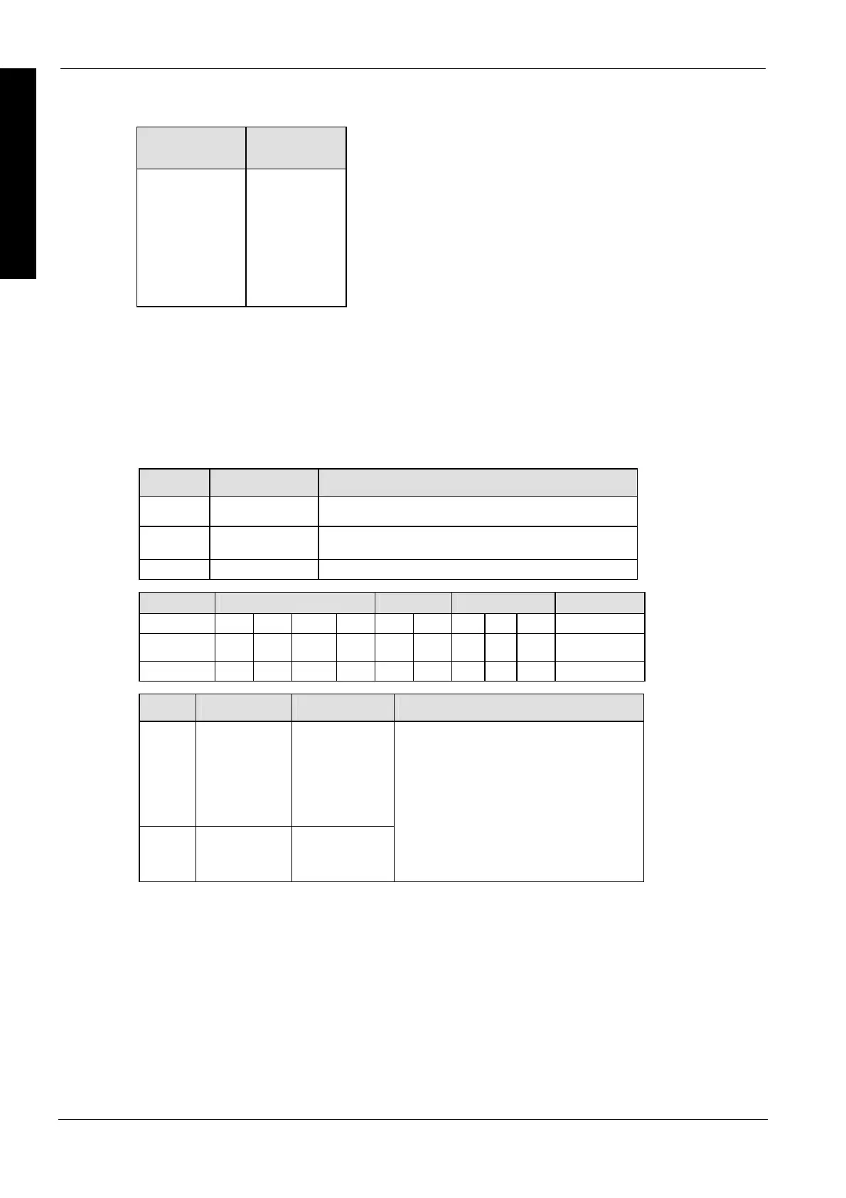
BCD character ASCII HEX
code
0
1
2
3
4
5
6
7
8
9
H30
H31
H32
H33
H34
H35
H36
H37
H38
H39
This instruction also exists as a P instruction (for FP2/2SH, FP3/5, FP10/10SH PLC types), which
is only executed at the rising edge of the EN trigger. Select [Insert P instruction] from the
"Instructions" pane if you require a P instruction. To facilitate reuse, the instruction then appears
under "Recently used" in the pop-up menu. Press <Ctrl>+<Shift>+<v> within the programming
area to open the list of recently used elements.
PLC types
Availability of F74_A2BCD (see page 1326)
Variable Data type Function
s1 WORD starting 16-bit area for storing ASCII code (source)s
s2 ANY16 specifies number of source data bytes to be converted, and
how it is arranged
d WORD starting 16-bit area for storing converted result (destination)
For Relay T/C Register Constant
s1 WX WY WR WL SV EV DT LD FL -
s2 WX WY WR WL SV EV DT LD FL dec. or hex.
d - WY WR WL SV EV DT LD FL -
No. IEC address Set If
R9007 %MX0.900.7 permanently
R9008 %MX0.900.8 for an instant
ASCII code not corresponding to decimal
numbers (0 to 9) is specified.
the number of bytes specified by s2
exceeds the area specified by s1.
the converted result exceeds the area
specified by d.
the data specified by s2 is recognized as
"0".
the number of bytes for ASCII characters
in s2 is more than 16#8.
Data types
Operands
Error flags
Example
In this example, the same POU header is used for all programming languages. For an example
using IL (instruction list), please refer to the online help.

 Loading...


