Counter instructions
703
Part III FP Instructions
In order to work correctly, the CT_FB function block needs to be reset
each time before it is used.
The number of available counters is limited and depends on the
settings in the system registers 5 and 6. The compiler assigns a NUM*
address to every counter instance. The addresses are assigned
counting downwards, starting at the highest possible address.
The basic CT (see page 704) function (down counter) uses the same
NUM* address area
(Num* input). In order to avoid errors (address
conflicts), the CT function and the CT_FB function block should not be
used together in a project.
Example
In this example, the same POU header is used for all programming languages. For an example
using IL (instruction list), please refer to the online help.
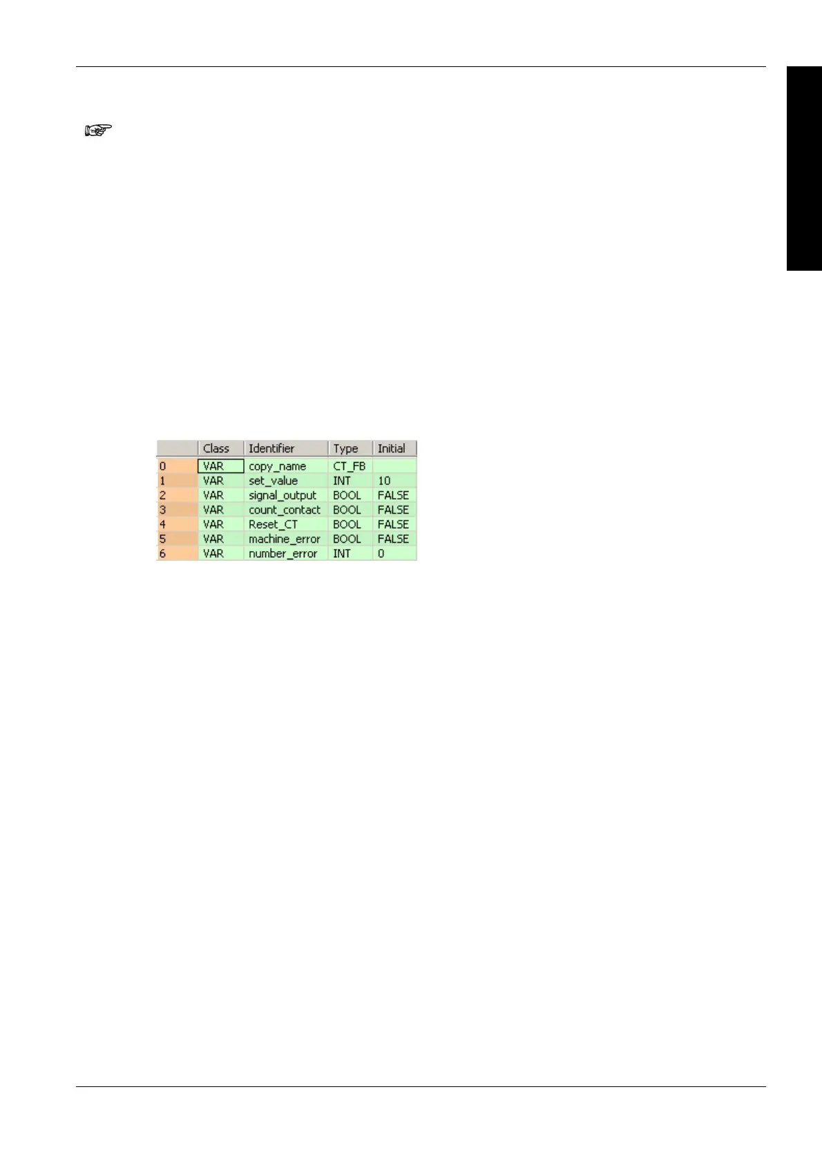
POU header
All input and output variables which are used for programming the function block CT_FB are
declared in the POU header. This also includes the function block (FB) itself. By declaring the FB
you create a copy of the original FB. This copy is saved under copy_name, and a separate data
area is reserved.

 Loading...


