High-speed counter instructions
909
Part III FP Instructions
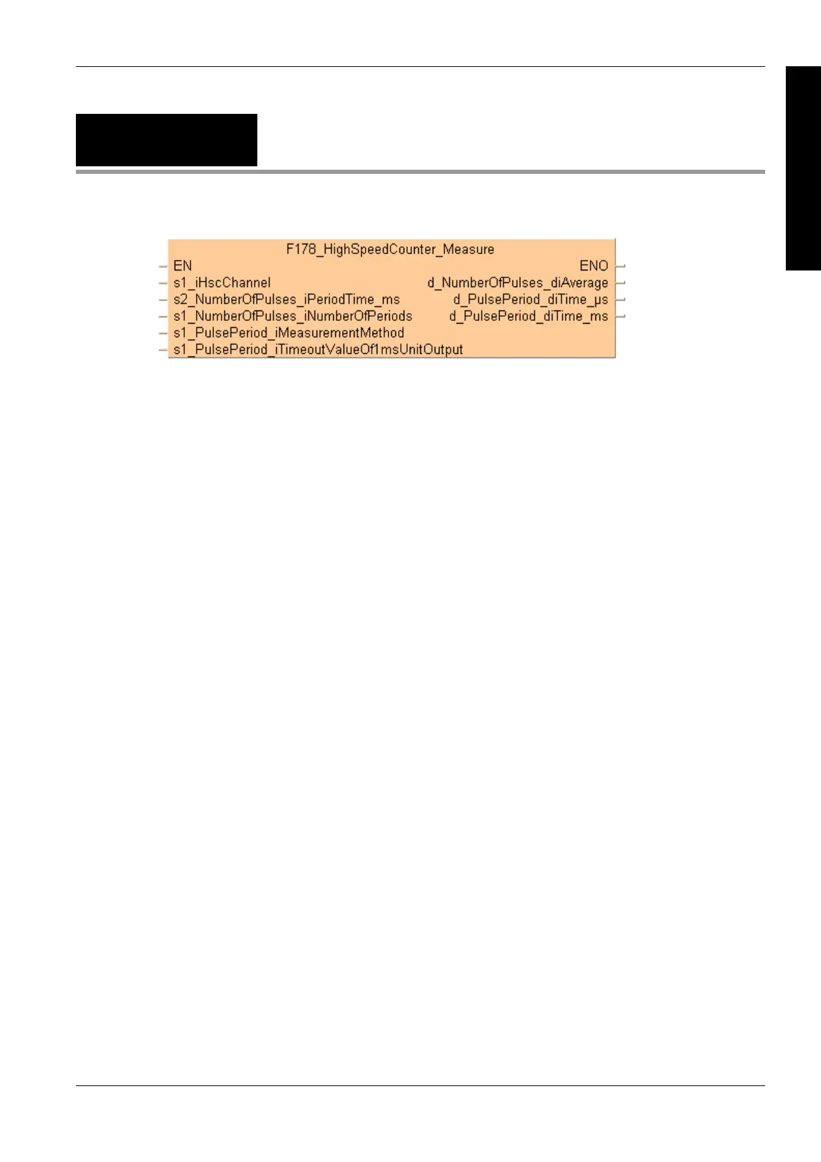
F178_HighSpeed
Counter_Measure
Input pulse measurement
Characteristics of input pulse measurement
For input pulse measurement, the channel number, the counting period (1ms–5s)
and the number of counting periods (1–5) must be specified. These parameters
are used to calculate the average number of input pulses per counting period.
The unit of pulse period measurement ([s], [ms] or both) can be specified.
If the measurement is in s, the pulse period is measured and output
immediately upon execution of this instruction. A maximum of approx. 174.4ms
can be measured.
If the measurement is in ms, the value of the pulse period is updated after every
measurement. A maximum of approx. 49.7 days can be measured. A time-out
value can be specified after which the measured pulse period is set to -1 if
measurement has not been completed.
During the first counting periods after starting the instruction, the measured pulse
period is set to -1 until the specified number of counting periods has been
reached.
If the pulse period is longer than the measurable range or if measurement has
not been completed, the measured pulse period is set to -1.
General programming information
Select the high-speed counter input for the desired channel in the system
registers.
Keep the execution condition TRUE for pulse measurement using this instruction.
To stop the measurement, turn the execution condition to FALSE.
When a high-speed counter instruction is executed, the high-speed counter
control flag (e.g. sys_bIsHscChannel0ControlActive) for the channel used turns
to TRUE. No other high-speed counter instruction using the same channel can
be executed as long as the control flag is TRUE.
The instruction can be executed simultaneously on a maximum of two channels.
If both the main program and the interrupt program contain code for the same
channel, make sure both are not executed simultaneously.
The status of the high-speed counter control flag or pulse output control flag may
change while a scan is being carried out. For example, if the flag is used more
than once as an input condition, different statuses may exist within one scan. To
ensure proper execution of the program, the status of the special internal relay
should be copied to a variable at the beginning of the program.
Description
This instruction measures the number of input pulses in a specified counting period and the pulse
period.

 Loading...


