EasyManuals Logo

Panasonic FP Series User Manual

Panasonic FP Series
1345 pages
To Next Page IconTo Next Page
To Previous Page IconTo Previous Page
Page #987 background imageLoading...
Page #987 background image
System register instructions
986
Part III FP Instructions
The values entered at s* will be right aligned automatically by the compiler.
This sets the interrupt input based on the contents specified by the character constant.
This sets the input specified by the first keyword as the interrupt input, and changes the input
conditions to the contents specified by the second keyword. The first and second keywords are
separated by a comma.
Keyword setting
INT2, UP
Effective edges
Interrupt Input
INT0: X0
INT2: X2
INT4: X4
INT6: X6
UP: Rising edge
DOWN: Falling edge
Both: Rising and falling edged
INT1: X1
INT3: X3
INT5: X5
INT7: X7
For the FP-X you can set INT0 to INT13.
Body
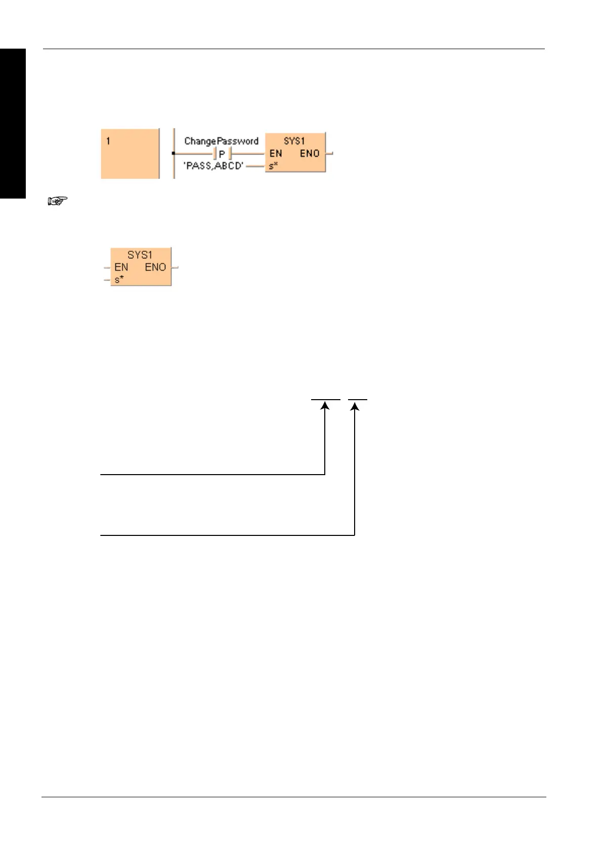
When ChangePassword turns on, the controller password is changed to "ABCD".
LD
Interrupt
Setting

Table of Contents

Other manuals for Panasonic FP Series

Questions and Answers:

Question and Answer IconNeed help?

Do you have a question about the Panasonic FP Series and is the answer not in the manual?

Panasonic FP Series Specifications

General IconGeneral
MountingDIN rail
TypePLC
Communication InterfaceRS-232, RS-485, Ethernet (depending on model)
Input Voltage100-240V AC or 24V DC (depending on model)
Output TypeRelay, Transistor
I/O PointsVaries by model
Operating Temperature0°C to 55°C
DimensionsVaries by model
WeightVaries by model

Related product manuals