EM500 Open-Loop Vector Control Inverter User Manual
283
input by AI1 analog quantity: When the AI1 analog quantity input is positive, the forward
speed amplitude limiting upper limit frequency value is AI1 (percentage) * F13.09,
The reverse speed amplitude limiting upper limit frequency value is AI1 (percentage) *
F13.09*F13.18; When the AI1 analog quantity input is negative, the forward speed
amplitude limiting upper limit frequency value is AI1 (percentage) * F13.09*F13.18
The reverse speed amplitude limiting upper limit frequency value is AI1 (percentage) *
F13.09.
Torque control maximum operating frequency = torque control upper limit
frequency + upper limit frequency offset (only F13.08 = 1 ~ 5 effective), but the
maximum operating frequency by F00.16 maximum frequency limit
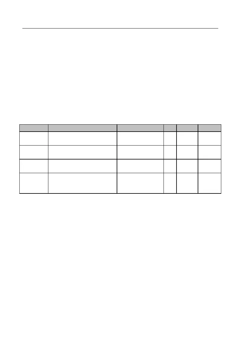
Static Friction Torque
Compensation
Static Friction Compensation
Frequency Range
Kinetic Friction Torque
Compensation
In driving an object, motor must overcome the static/kinetic friction. Setting this
group of parameters can enable the torque to rotate as per the specified torque after
having overcome the inherent static/kinetic friction force. The static friction prevails
before motor runs, but the kinetic friction prevails after motor runs. All in all, this group
of parameters is related to motor capacity performance.
When the actual frequency (estimated frequency if inverter is in the SVC control
mode) is less than or equal to the value set through F13.12, then the output torque is “set
frequency + F13.11 Static Friction Torque Compensation”. When the actual frequency is
greater than the value set through F13.12, the output torque is “Set Torque + F13.13
Kinetic Friction Torque Compensation”. The greater the compensation is, the higher the
compensation level will be. The percentage of the compensation is equal to the torque
setting percentage.
 Loading...


