EM500 Open-Loop Vector Control Inverter User Manual
287
Acceleration/Deceleration
Time Reference
Frequency
0: Maximum Frequency
F00.16
1: 50.00Hz
As for normal running (non jog running), the system offers 4 groups of
acceleration/deceleration time options (first group F00.14 and F00.15) to meet different
demands. After setting, user may switch between the numeric input mode “19:
Acceleration/Deceleration Time Terminal 1” and “20: Acceleration/Deceleration Time
Terminal 2”. See Table 7–4 Numeric Multi-Function Input Terminals”
t
Output
Frequency
0
Acceleration/
Deceleration Time
Reference Frequency
F15.09
Set Deceleration Time
Set Acceleration
Time
Actual Acceleration Time Actual Deceleration Time
Set Frequency
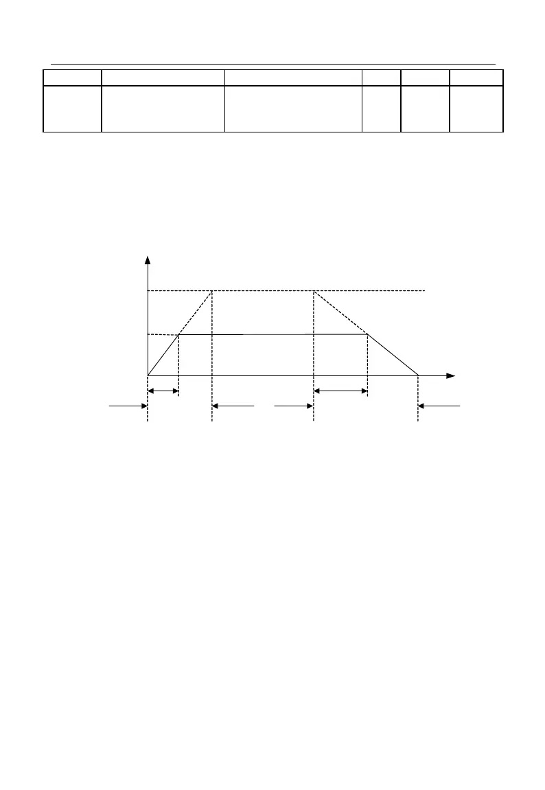
Figure 7-33 Acceleration/Deceleration Time
As indicated in Figure 7-33, the defined acceleration time refers to the time that the
frequency increases from 0.00 Hz to the acceleration/deceleration time reference
frequency; the deceleration time refers to the time that the frequency decreases from the
acceleration/deceleration time reference frequency to 0.00 Hz. Actual
acceleration/deceleration time depends upon the ratio of the set frequency to the reference
frequency.
F15.09 is used to set the acceleration/deceleration time reference frequency. If
F15.09=0, the reference frequency is set by F00.16 (maximum frequency). If also
F00.16=100.00 Hz, the acceleration time refers to the time that output frequency
increases from 0.00 Hz (100.00 Hz) to 100.00 Hz (0.00 Hz), and the deceleration time
refers to the time that output frequency decreases from 100.00 Hz (0.00 Hz) to 0.00 Hz