3-10
IM 701210-05E
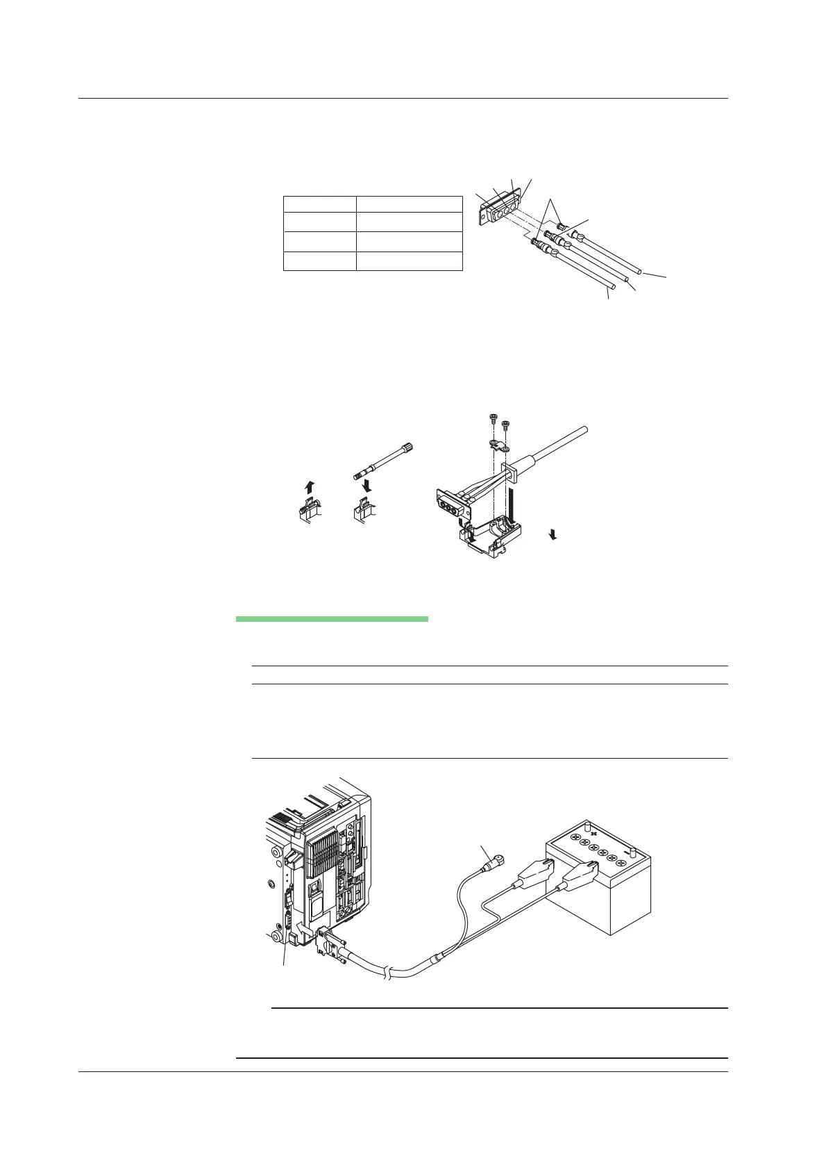
6. Insert the terminal tips into the terminal block as shown in the figure. The
connector numbers and power polarities are listed below.
1
2
3
Positive
Negative
GND
Terminal No. Signal
1 Positive
2 Protective ground
3 Negative
Terminal block
Tip with a large diameter
Tip with a small diameter
7. Replace the attachment screws as necessary. You can remove the attachment
screws by pulling the screws in the direction of the arrow.
8. Attach the cable
25,
to the connector. Set the chip mount flange and cable cover flange in the connector
case grooves. Secure the cable in place using the cable retainer.
9. Put the connector case on and fasten it with screws.
Connecting to the Power Supply
Connect the power cord as shown in the figure below. The power supply must meet the
following conditions:
Item
Rated supply voltage 12 VDC
Permitted supply voltage range 10 to 18 VDC (at the DL750/DL750P connector end)
Maximum power consumption Approx. 120 VA Max.
(Reference value: 80 VA when the built-in printer is not used
and 16 channels are running)
Connect to protective
earth ground
Battery
DC power connector
Note
• If both AC power and DC power are supplied, AC power takes precedence.
• If both AC power and DC power are supplied and AC power is cut off, the power
instantaneously switches to DC power.
3.4 Connecting the Power Supply

 Loading...


