5-31
IM 701210-05E
Horizontal and Vertical Axes
5
5.17 Setting the Strain Measurement
<For a description of this function, refer to page 2-14.>
Procedure
MEASURE
CURSOR RESET SELECT
CH
ALL CH
MODE
POSITION
SIMPLE/ENHANCED
ACQ
START/STOP
SETUP DISPLAY
ZOOM
DUAL
CAPTURE
HISTORY
MATH
1
CH
2
CH
3
CH
4
CH
5
CH
6
CH
7
CH
8
CH
9
CH
10
CH
11
CH
12
CH
13
CH
14
CH
15
CH
16
DELAY
MANUAL TRIG
V/DIV TIME/DIV
TRIGGER
TRIG D
VERTICAL
HORIZONTAL
CAL
X-Y
SEARCH
7
DSP 1
8 9
DSP 2
654
1
0
23
ENTER
m
DSP 6DSP 5
LOGIC A
LOGIC B
EVENT
DSP 3 DSP 4
EXP
GO/NO-GO
ACTION
FILE
SHIFT
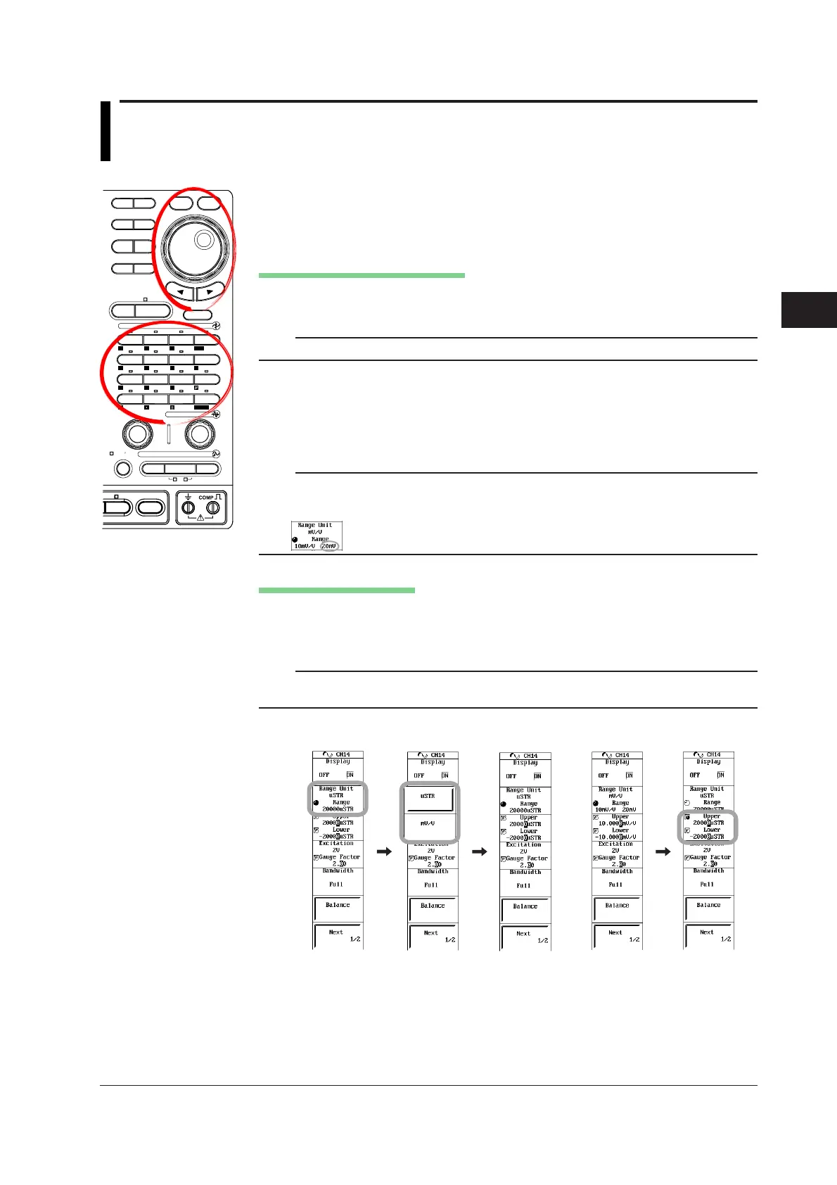
1. Press a key from CH1 to CH16 keys to select the desired channel (select a
channel with the Strain Module (701270 (STRAIN_NDIS) or 701271
(STRAIN_DSUB)) installed).
Selecting the Measurement Range
2. Press the Range Unit soft key, and then press the µSTR (the unit of strain) or
mV/V (the unit of the output value of the strain gauge transducer) soft key.
Note
Be sure to execute balancing when you change the measurement range.
• When µSTR Is Selected
3. Use the jog shuttle to select the Range from 500 µSTR to 20000 µSTR.
• When mV/V Is Selected
3. Use the jog shuttle to select the Range from 0.25 mV/V to 10 mV/V.
Note
If the range unit is set to mV/V, a numeric value is displayed at the right side of the range
display. This value is the maximum input at the current bridge voltage converted to volts. It
indicates the maximum input voltage at the selected range.
Setting the Display Range
4. Press the Upper/Lower soft key to set the jog shuttle control to Upper.
5. Turn the jog shuttle to set the upper limit.
6. Likewise, set Lower.
Note
Pressing RESET sets the upper and lower limits to the maximum and minimum values of the
measurement range.
When Range
Unit is µSTR
When Range
Unit is mV/V

 Loading...


