1-10
IM 701210-05E
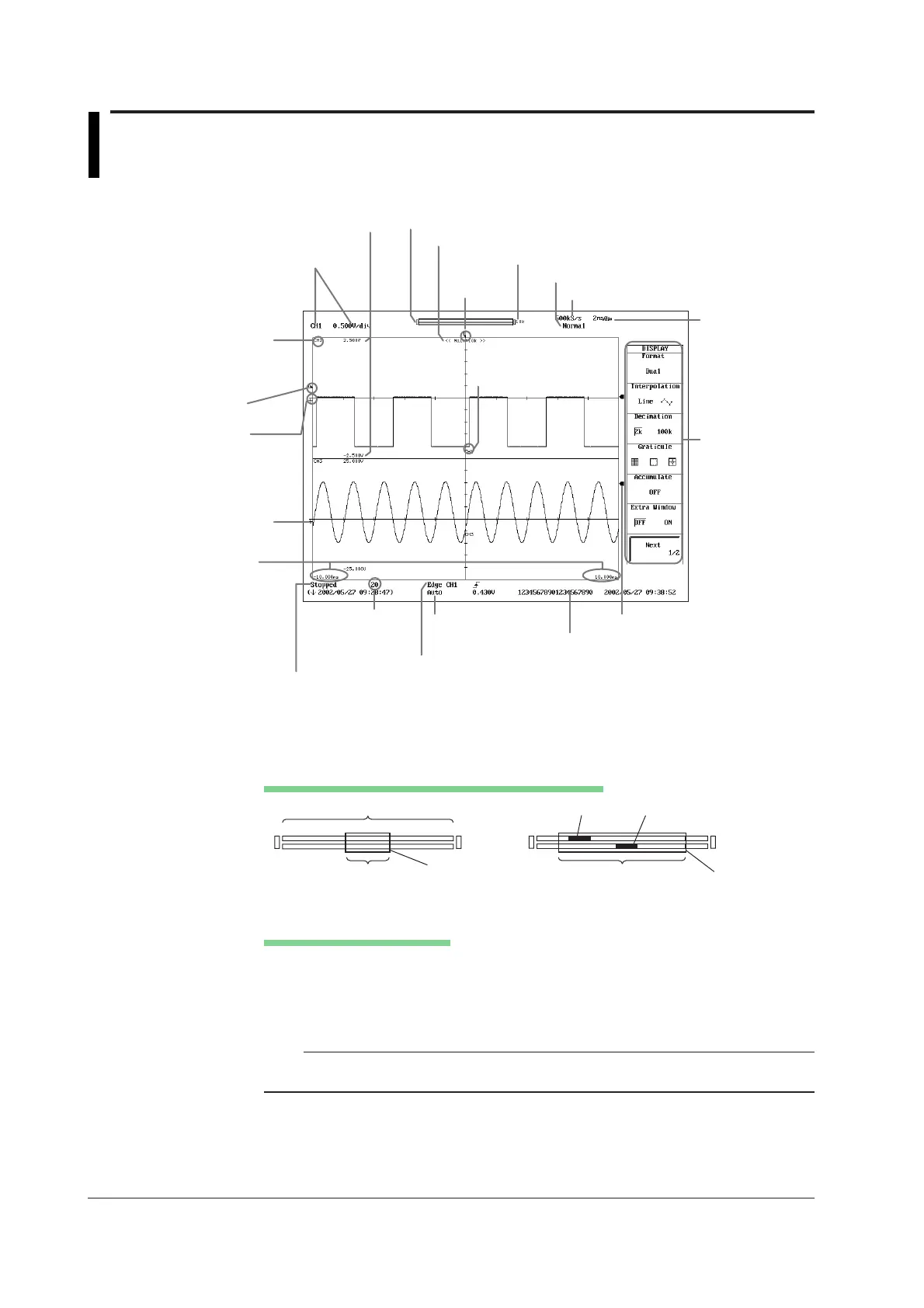
1.3 Display Screens
Normal Waveform Display
Waveform acquisition condition
Number of
waveform
acquisitions
(section 7.3)
Comment
(Sections 12.2 to 12.4, and 13.11)
Trigger mode
(section 6.1)
Setup channel and the
V/div (section 5.3)
Stopped Pre...: Acquiring pre data
Running Post...: Acquiring post data
Waiting for trigger
HD out: Continuous writing to hard disk
Record length (section 7.2)
Acquisition mode (See the explanation below.)
Sample rate
T/div (section 5.2)
Trigger
position
Display record length (appendix 1)
Trigger level
(chapter 6)
Ground level
(chapter 6)
Channel number
of the display range
Scale value of the voltage axis
Vertical position
(section 5.4)
Time from the
trigger position
(section 6.2)
Trigger type (chapter 6)
Soft key menu
Level indicator
Channel number of
the display waveform
Record length and display position (see the explanation below)
Displaying the Record Length and Display Position
Specified record length
Display record length
Display record length
Z1
Z2
Z2 zoom position
<When displaying zoom waveforms>
<When displaying normal waveforms>
2.5M
Green frame
Green frame
2.5M
Z1 zoom position
Acquisition Mode Indication
Normal: Normal mode
Env: Envelope mode
Avg: Average mode
BoxAvg: Box average mode
Note
In some cases, the LCD on the DL750/DL750P may include few defective pixels. For details,
see section 19.4, “Display.”

 Loading...


