5-14
IM 701210-05E
5.9 Zooming Vertically According to the Upper and
Lower Limits of the Display Range
<For a description of this function, refer to page 2-7.>
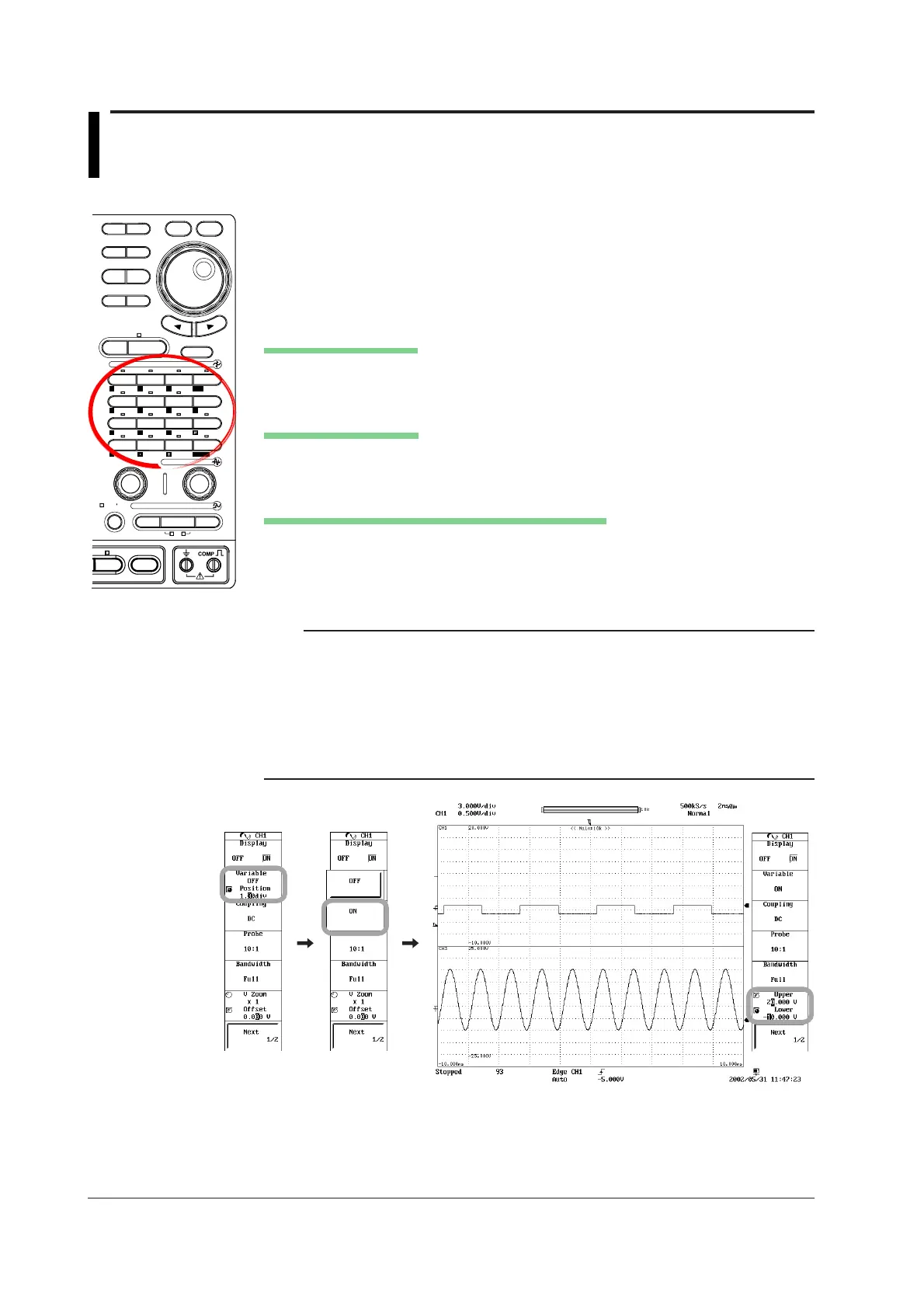
Procedure
MEASURE
CURSOR RESET SELECT
CH
ALL CH
MODE
POSITION
SIMPLE/ENHANCED
ACQ
START/STOP
SETUP DISPLAY
ZOOM
DUAL
CAPTURE
HISTORY
MATH
1
CH
2
CH
3
CH
4
CH
5
CH
6
CH
7
CH
8
CH
9
CH
10
CH
11
CH
12
CH
13
CH
14
CH
15
CH
16
DELAY
MANUAL TRIG
V/DIV TIME/DIV
TRIGGER
TRIG D
VERTICAL
HORIZONTAL
CAL
X-Y
SEARCH
7
DSP 1
8 9
DSP 2
654
1
0
23
ENTER
m
DSP 6DSP 5
LOGIC A
LOGIC B
EVENT
DSP 3 DSP 4
EXP
GO/NO-GO
ACTION
FILE
SHIFT
1. Press a key from CH1 to CH16 keys to select the desired channel.
To select a DSP channel (optional), press SHIFT + CH1 (DSP1) through SHIFT
+ CH6 (DSP6).
2. Press the Variable/Position soft key. The Variable selection menu appears.
3. Press the ON soft key.
Setting the Upper Limit
4. Press the Upper/Lower soft key to set the jog shuttle control to Upper.
5. Turn the jog shuttle to set the upper limit.
Setting the Lower Limit
6. Press the Upper/Lower soft key to set the jog shuttle control to Lower.
7. Turn the jog shuttle to set the lower limit.
Setting the Upper and Lower Limits Simultaneously
8. Press the Upper/Lower soft key to set the jog shuttle control to both Upper and
Lower.
9. Turn the jog shuttle to set the upper and lower limits without changing the
spacing between the two.
Note
Pressing RESET sets the maximum and minimum values of the measurement range to the
upper and lower limits.
• When observing voltage Upper: 10 times +V/div, Lower: 10 times –V/div
• When observing strain Upper: +FS, Lower: –FS
• When measuring acceleration Upper: 5000/(gain × sensitivity)
Lower: –5000/(gain × sensitivity)
• When measuring frequency and other parameters on the frequency module
Upper: (Offset value) + (Value/div × 30)
Lower: (Offset value) – (Value/div × 30)

 Loading...


