3-32
IM 701210-05E
3.13 Connecting Sensors to the Frequency Module
Sensors and Signal Output Sources That Can Be Connected
The table below shows the sensor and signal output source that can be connected.
Appropriate input presets are provided for each sensor and signal output source. For the
setup procedure of presets, see page 5-40.
Sensor and Signal Output Source Preset Name
5-V logic signal, 5-V output sensor, and sensor with TTL output Logic 5V
3-V logic signal and 3-V output sensor Logic 3V
12-V driven relay/sequence circuit and 12-V driven sensor Logic 12V
24-V driven relay/sequence circuit and 24-V driven sensor Logic 24V
Sensor/Encoder that outputs positive and negative voltages and sensor ZeroCross
that outputs sine waves
100-VAC power supply (connected via the isolated probe (700929)) AC100V
200-VAC power supply (connected via the isolated probe (700929)) AC200V
Power-generating electromagnetic pickup EM Pickup
Open collector output (0 to 5 V output) and contact output Pull-up 5V*
* For the internal equivalent circuit for “Pull-up 5V,” see page 5-50.
Precautions to Be Taken When Connecting to Sensors or Signal Output Sources
CAUTION
• The maximum input voltage for direct input is indicated below. Applying a
voltage exceeding this value can damage the input section. If you are applying
high voltage that exceeds 42 V, be sure to use the isolated probe (700929).
Maximum input voltage: 42 V (DC+ACpeak) (CAT I and CAT II)
• The minimum input voltage is 0.2 Vpp. At voltage amplitude less than 0.2 Vpp,
the measured values may be unstable.
• Attach/Remove the sensors after confirming that the rotating object to be
measured is stopped.
• Set the preset to electromagnetic pickup (EM Pickup) only when using the
electromagnetic pickup.
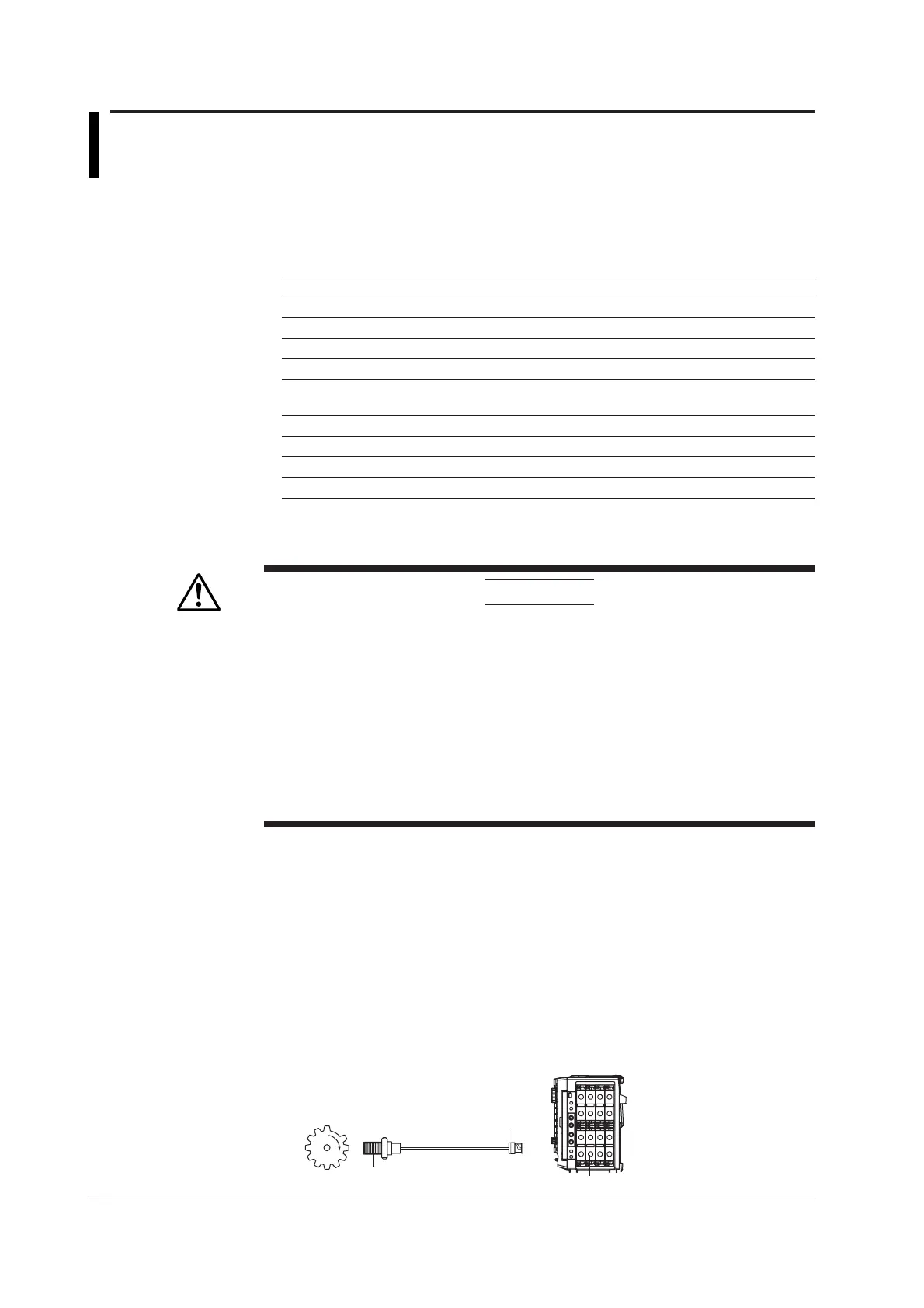
Connecting the Electromagnetic Pickup
• The DL750/DL750P allows power-generating electromagnetic pickup to be connected
directly. The DL750/DL750P does not support electromagnetic pickups that require
external power supply or those that require a terminator at the output.
• To connect electromagnetic pickups, use BNC cables. Use cables that are
appropriate for the electromagnetic pickups being used.
• When the input is set to electromagnetic pickup, determination is not made on
whether the input voltage level exceeds the specified input voltage range. Therefore,
the LEDs (see page 3-7) do not illuminate even when the input voltage level is over
range.
701280 (FREQ)
Power-generating
electromagnetic pickup
Rotating object
to be measured
BNC connector
DL750/DL750P

 Loading...


