8-12
IM 701210-05E
8.6 Displaying X-Y Waveforms
<For a description of this function, refer to page 2-40.>
Procedure
MEASURE
CURSOR RESET SELECT
CH
ALL CH
MODE
POSITION
SIMPLE/ENHANCED
ACQ
START/STOP
SETUP DISPLAY
ZOOM
DUAL
CAPTURE
HISTORY
MATH
1
CH
2
CH
3
CH
4
CH
5
CH
6
CH
7
CH
8
CH
9
CH
10
CH
11
CH
12
CH
13
CH
14
CH
15
CH
16
DELAY
MANUAL TRIG
V/DIV TIME/DIV
TRIGGER
TRIG D
VERTICAL
HORIZONTAL
CAL
X-Y
SEARCH
7
DSP 1
8 9
DSP 2
654
1
0
23
ENTER
m
DSP 6DSP 5
LOGIC A
LOGIC B
EVENT
DSP 3 DSP 4
EXP
GO/NO-GO
ACTION
FILE
SHIFT
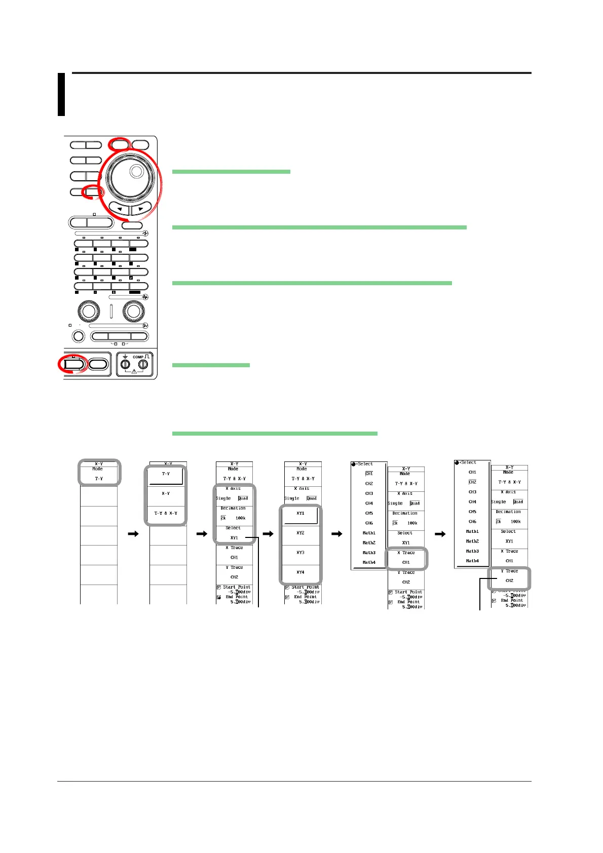
1. Press SHIFT+DISPLAY. The X-Y menu appears.
Selecting the Display Mode
2. Press the Mode soft key. The mode selection menu appears.
3. Press the T-Y, X-Y, or T-Y&X-Y soft key to set the mode.
Setting the Number of Data Points to Be Used for Waveform Display
4. Press the Decimation soft key to select the number of points to be used for the
display from 2k and 100k.
Selecting the X Axis Mode (When Mode Is Set to X-Y or T-Y&X-Y)
5. Press the X Axis soft key to select Single or Quad.
If you select Single proceed to step 8; if you select Quad proceed to step 6.
6. Press the Select soft key. The X-Y waveform selection menu appears.
7. Press the soft key corresponding to the desired X-Y waveform from XY1 to XY4.
Setting the X Axis
8. Press the X Trace soft key. The channel selection menu appears.
9. Use the jog shuttle and SELECT to select the channel to be assigned to the X
axis. If you set X Axis to Quad, proceed to step 10.
Setting the Y Axis (When X Axis Is Set to Quad)
10. As with the X axis, press the Y Trace soft key to set the Y axis.
When X Axis: Quad
When X Axis: QuadDSP1 to DSP6 are optional.

 Loading...


