App-14
IM 701210-06E
Appendix 5 User-Defined Computation
Digital Filter
Type
Type Bandwidth
Gaussian LowPass
Sharp LowPass/HighPass/BandPass
IIR (Butterworth) LowPass/HighPass/BandPass
Filter Order
See the following table for the filter orders
2% 5% 10% 20% 30% (Cutoff)
Gauss LowPass 49 21 9 5 5
Sharp LowPass 88 36 18 9 8
HighPass 159 65 33 17 13
IIR LowPass 4 4 4 3 2
HighPass 4 4 4 4 3
Filter Characteristics
Filter Pass-band Attenuation Slope Attenuation at the Phase
Ripple Stop-band
Gauss 0dB
1
– Linear phase
Sharp ±0.3 dB –40 dB at 1 oct (Lowpass), –40 dB Linear phase
–40 dB at –1oct (Highpass)
IIR 0 dB –5 dB at 1/6 oct (Lowpass), Not linear phase
–20 dB at –1 oct (Highpass) –
1. For Gaussian filter : –3.0× (f/fc) 2 dB (f : frequency, fc : cutoff frequency)
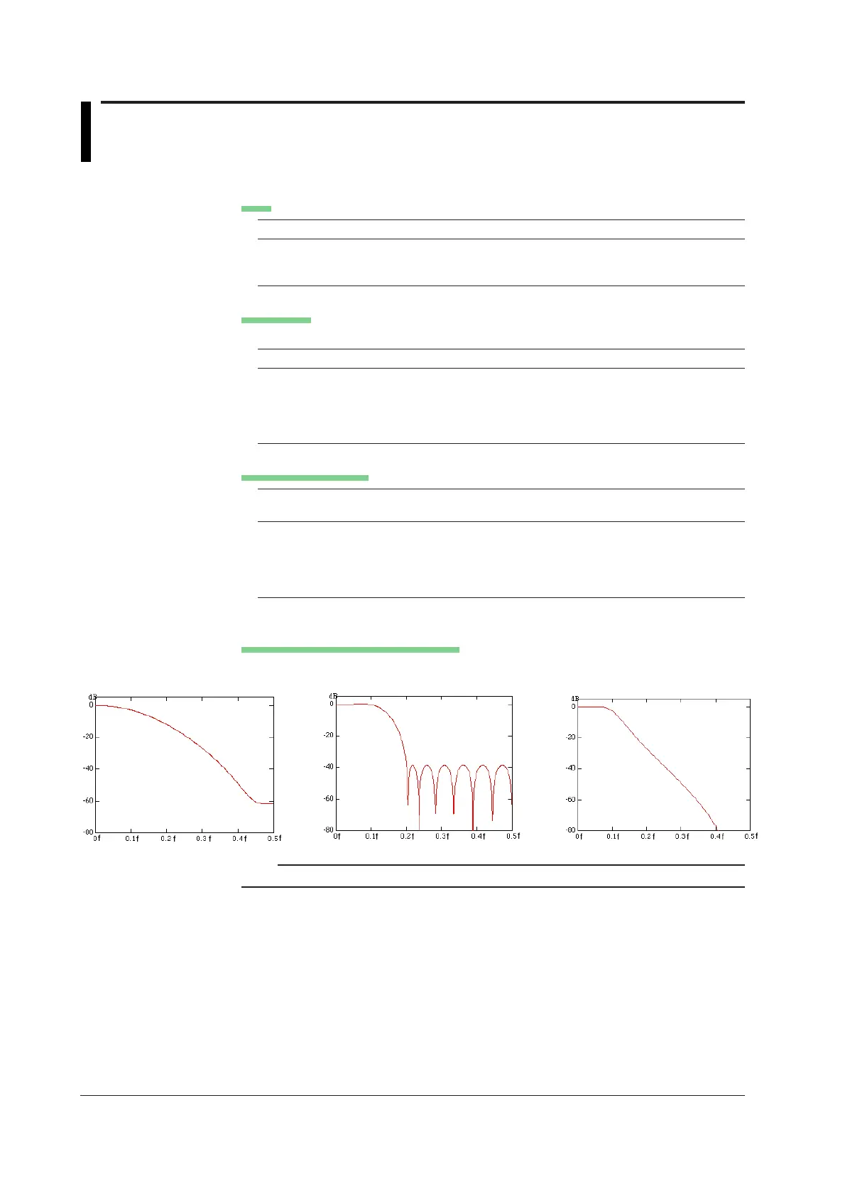
Frequency Characteristics of Filters
f: Sampling frequency (Hz)
Gauss(Cutoff: 10%) Sharp(Low Pass, Cutoff: 10%) IIR(Low Pass, Cutoff: 10%)
Note
The higher the filter order the longer it takes for computation.

 Loading...


