5-7
IM 701210-05E
Horizontal and Vertical Axes
5
5.5 Setting the Input Coupling
<For a description of this function, refer to page 2-8.>
Procedure
MEASURE
CURSOR RESET SELECT
CH
ALL CH
MODE
POSITION
SIMPLE/ENHANCED
ACQ
START/STOP
SETUP DISPLAY
ZOOM
DUAL
CAPTURE
HISTORY
MATH
1
CH
2
CH
3
CH
4
CH
5
CH
6
CH
7
CH
8
CH
9
CH
10
CH
11
CH
12
CH
13
CH
14
CH
15
CH
16
DELAY
MANUAL TRIG
V/DIV TIME/DIV
TRIGGER
TRIG D
VERTICAL
HORIZONTAL
CAL
X-Y
SEARCH
7
DSP 1
8 9
DSP 2
654
1
0
23
ENTER
m
DSP 6DSP 5
LOGIC A
LOGIC B
EVENT
DSP 3 DSP 4
EXP
GO/NO-GO
ACTION
FILE
SHIFT
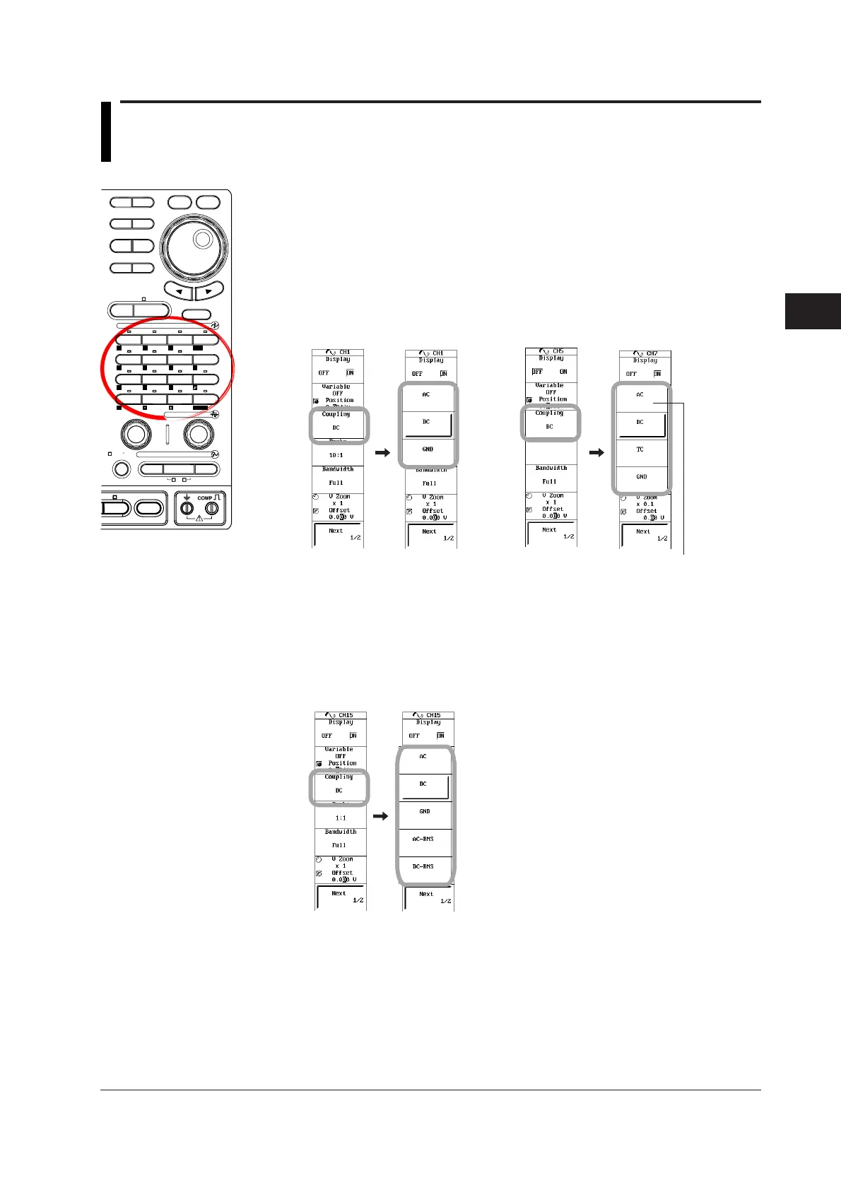
1. Press a key from CH1 to CH16 keys to select the desired channel.
2. Press the Coupling soft key. The coupling selection menu appears.
3. Press the soft key corresponding to the desired coupling.
When observing temperature using the 701265 (TEMP/HPV), select TC.
For the setup procedure of temperature measurements, see section 5.16.
AC is not available on the 701265.
Input module:
701250(HS10M12)/701251(HS1M16)/
701255(NONISO_10M12)
Input module:
701261(UNIVERSAL)/
701262(UNIVERSAL(AAF))/
701265(TEMP/HPV)
When observing rms values using the 701260 (HV (with RMS)), select AC-RMS
or DC-RMS.
For the setup procedure of rms measurements, see section 5.15.
Select ACCL when measuring acceleration on the 701275 (ACCL/VOLT). For
the setup procedure of acceleration measurements, see section 5.18.
Input module:
701260(HV(with RMS))

 Loading...


