2-19
IM 701210-05E
Explanation of Functions
2
Logic Waveforms <Section 5.20>
Logic waveforms can be measured by connecting logic probes to the logic signal input
connectors (two connectors marked LOGIC A and LOGIC B) on the left side panel. A-1
to A-8 (8 bits) and B-1 to B8 (8 bits) can be input to the LOGIC A and LOGIC B ports,
respectively.
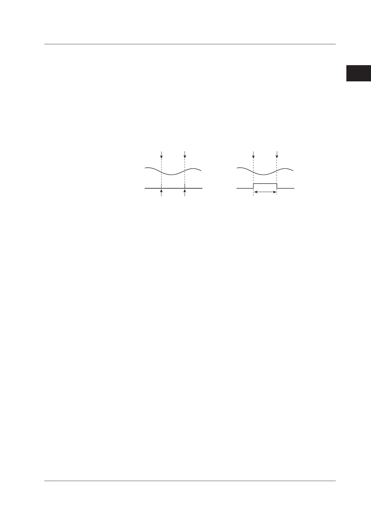
Event Waveforms <Section 5.21>
The times when triggers are activated with the dual capture function and the period
during which voice memos are recorded can be displayed as events.
High-speed waveform
(sub waveform) is acquired
here.
Event
Main
waveform
Trigger
Trigger
• Events during dual capture
Event
Target
waveform
Record start
Record end
• Events on voice memos
Period during which the voice
memo is recorded
(Between the rising edge and
the falling edge)
2.2 Setting the Horizontal and Vertical Axes

 Loading...


