App-26
IM 701210-06E
Appendix 6 DSP Channel Computation (Optional)
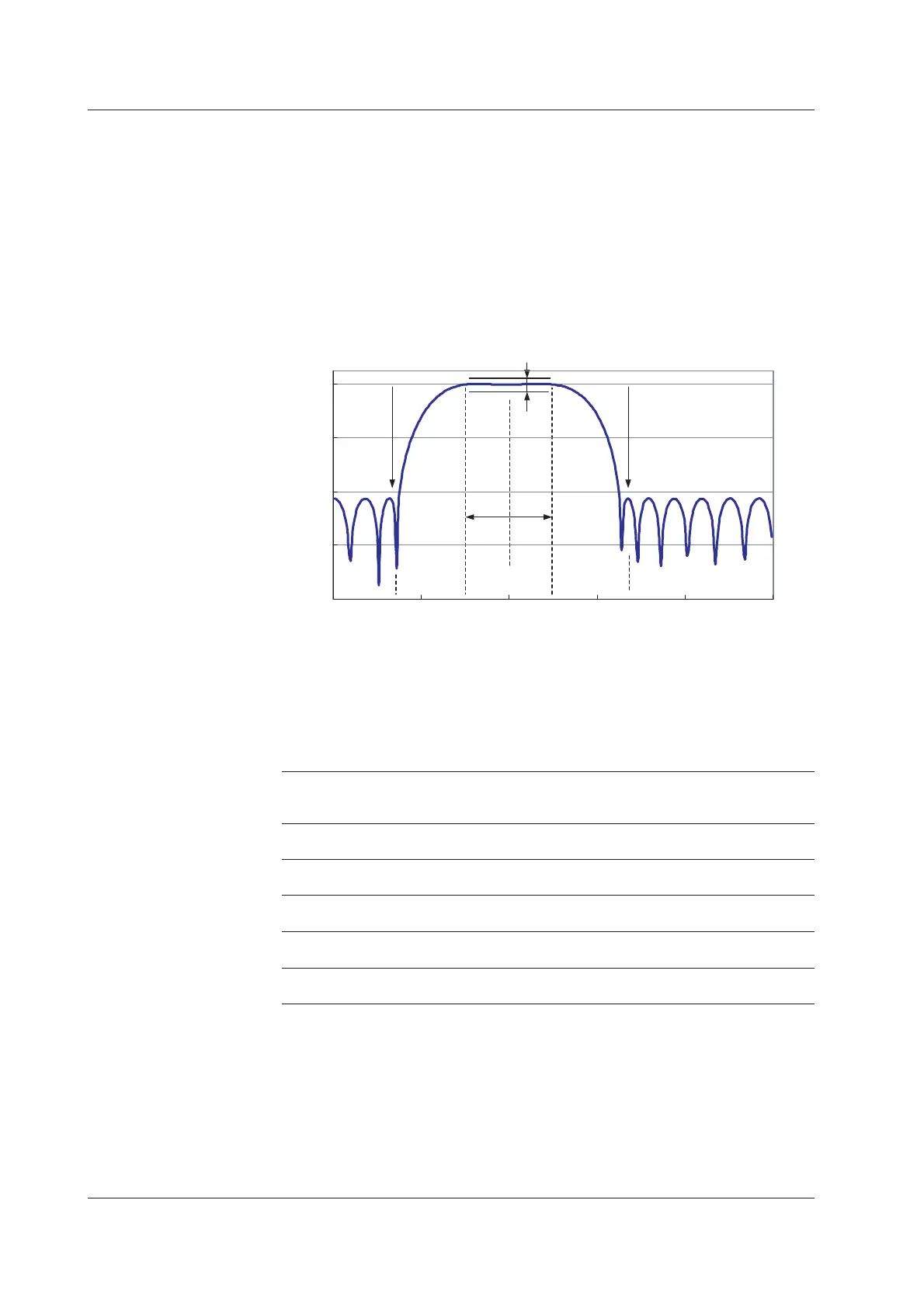
• Bandpass
• The ripple in the pass band is within 0.3 dB.
• In the low frequency region, the attenuation falls to –40 dB at 1/2 the frequency
from the pass band edge f
cl
.
• The width of the transition region from the pass band edge in the high frequency
region to the –40 dB point is equal to the width of the transition region in the low
frequency region.
(f
cl
–1/2f
cl
= f
cus
–f
cu
)
• The attenuation in the stop band is –40 dB or greater.
• Has linear phase characteristics and constant group delay.
-80
-60
-40
-20
0
0 f 0.1 f 0.2 f 0.3 f 0.4 f 0.5 f
fcl fcu fcus1/2 fcl
(fcl–1/2 fcl) = (fcus–fcu)
Center
frequency
Passband
0.3 dB
-40 dB-40 dB
SHARP Band-pass Frequency Characteristics Example
dB
(f: sampling frequency [Hz])
For SHARP band-pass filters, the center frequency that can be specified is limited by the
pass-band width.
Selectable Range of SHARP Bandpass Filter Frequency
Passband Width Setting [%] Lower Limit of Center Upper Limit of Center
Frequency [%] Frequency [%]
(Passband Region) (Passband Region)
2330
(2 to 4) (29 to 31)
5 4.6 30
(2.1 to 7.1) (27.5 to 32.5)
10 7 30
(2 to 12) (25 to 35)
15 9.6 30
(2.1 to 17.1) (22.5 to 37.5)
20 12 30
(2 to 22) (20 to 40)

 Loading...


