1–4 Altera Corporation
Stratix Device Handbook, Volume 2 July 2005
Introduction
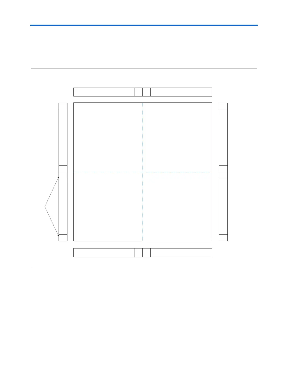
Figure 1–1 shows a top-level diagram of the Stratix device and PLL
floorplan. Figure 1–2 shows a top-level diagram of the Stratix GX device
and PLL floorplan. See “Clocking” on page 1–39 for more detail on PLL
connections to global and regional clocks.
Figure 1–1. Stratix PLL Locations
FPLL7CLK FPLL10CLK
FPLL9CLK
CLK8-11
FPLL8CLK
CLK0-3
7
1
2
8
10
4
3
9
115
126
CLK4-7
CLK12-15
PLLs