6–14 Altera Corporation
Stratix Device Handbook, Volume 2 July 2005
Architecture
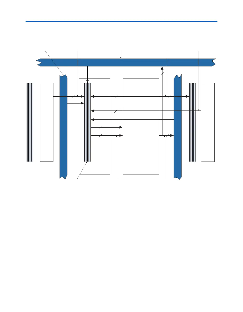
Figure 6–7. DSP Row Interface Block
Control Signals in the Row Interface Block
The DSP block has a set of input registers, a pipeline register, and an
output register. Each register is grouped in banks that share the same
clock and clear resources:
■ 1- to 9-bit banks for the input register
■ 1- to 18-bit banks for the pipeline register
■ 18 bits for the output register
LAB LAB
Row Interface
Block
DSP Block
Row Structure
10
[17..0][17..0]
DSP Block to
LAB Row Interface
Block Interconnect Region
18 Inputs per Row 18 Outputs per Row
R4 and R8 Interconnects
4 and
Int
r
nn
t
Dir
tLink Int
r
nn
rom Ad
acent LA
Nine DirectLink Outputs
to Adjacent LABs
DirectLink Interconnect
from Adjacent LAB
1818
9
10
3
Control
9
18