Altera Corporation 6–15
July 2005 Stratix Device Handbook, Volume 2
DSP Blocks in Stratix & Stratix GX Devices
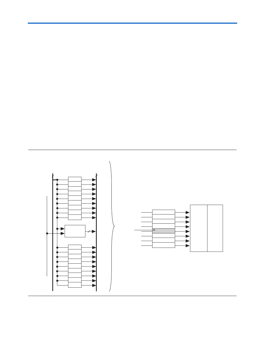
The row interface block generates the control signals and routes them to
the DSP block. Each DSP block has 18 control signals:
■ Four clock signals (clock[3..0]), which are available to each bank
of DSP blocks
■ Four clear signals (aclr[3..0]), which are available to each bank
of DSP blocks
■ Four clock enable signals (ena[3..0]), which the whole DSP block
can use
■ signa and signb, which are specific to each DSP block
■ addnsub[1..0] signals
■ accum_sload[1..0] signals
The signa, signb, and addnsub[1..0], accum_sload[1..0]
signals have independent clocks and clears and can be registered
individually. When each 18 × 18 multiplier in the DSP block splits in half
to two 9 × 9 multipliers, each 9 × 9 multiplier has independent control
signals. Figure 6–8 shows the DSP block row interface and shows how it
generates the data and control signals.
Figure 6–8. DSP Block Row Interface
DSP Row 1
DSP Row 2
DSP Row 3
DSP Row 4
DSP Row 5
DSP Row 6
DSP Row 7
DSP Row 8
DSP Block
Row Interface
Input
Registers
DSP
Block
Bit 0
Bit 1
Bit 2
Bit 3
Bit 4
Bit 5
Bit 6
Bit 7
Bit 8
DSP Row
Bit 9
Bit 10
Bit 11
Bit 12
Bit 13
Bit 14
Bit 15
Bit 16
Bit 17
DSP Row
21 Signals for
Data to Input
Register
DSP Row
Unit Control
Block
3
30 Local
Interconnect
Signals
LAB
Row
Clocks
Detail of
1 DSP Row