6–16 Altera Corporation
Stratix Device Handbook, Volume 2 July 2005
Architecture
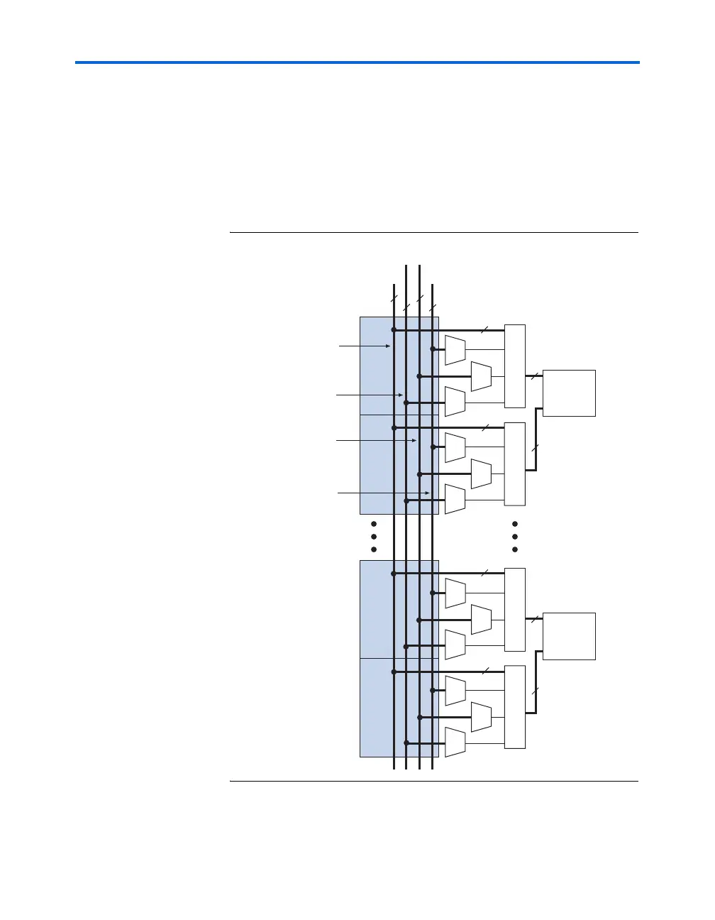
The DSP block interface generates the clock signals from LAB row clocks
or the local interconnect. The clear signals are generated from the local
interconnects within each DSP block row interface or from LAB row
clocks. The four clock enable signals are generated from the 30 local
interconnects from the same LAB rows that generate the clock signals.
The clock enable is paired with the clock because the enable logic is
implemented at the interface. Figure 6–9 shows the signal distribution
within the row interface block.
Figure 6–9. DSP Block Row Interface Signal Distribution
18 × 18
Multiplier
A1
B1
18
18
18
18
Row 1
Row 2
18 × 18
Multiplier
A4
B4
18
18
18
18
Row 7
Row 8
4
4
4
18
clock[3..0]
aclr[3..0]
ena[3..0]
data[17..0]
Input
Registers
18-Bit Data Routed
from 30 Local
Interconnects
Four Clock Enable
Signals Routed from
30 Local Interconnects
Four Clear Signals
Routed from 30 Local
Interconnects or LAB
Row Clock
Four Clock Signals
Routed from LAB
Row Clock or Local
Interconnect