7–32 Altera Corporation
Stratix Device Handbook, Volume 2 September 2004
Finite Impulse Response (FIR) Filters
where:
x
real
is the real input signal
x
imag
is the imaginary input signal
h
real
is the real filter coefficients
h
imag
is the imaginary filter coefficients
y
real
is the real output signal
y
imag
is the imaginary output signal
In complex representation, this equals:
The overall real channel output is obtained by adding the real channel
outputs of all the multipliers. Similarly, the overall imaginary channel
output is obtained by adding the imaginary channel outputs of all the
multipliers.
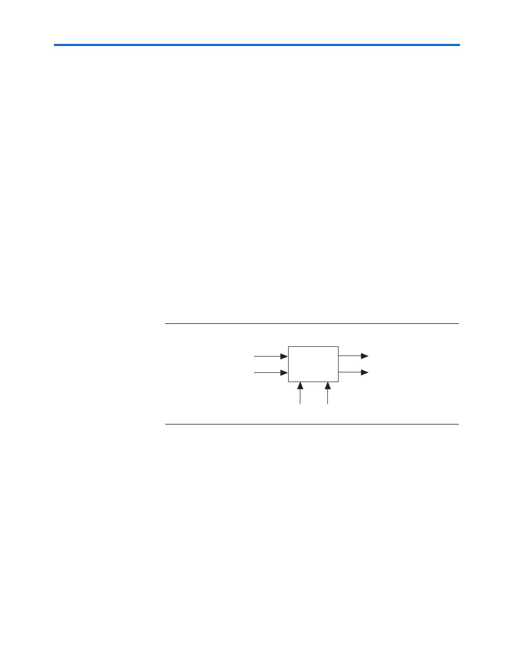
Figure 7–18. Complex FIR Filter Block Diagram
Complex FIR Filter Implementation
Complex filters can be easily implemented in Stratix devices with the DSP
blocks configured in the two-multipliers adder mode. One DSP block can
implement a 2-tap complex FIR filter with 9-bit inputs, or a single tap
complex FIR filter with 18-bit inputs. DSP blocks can be cascaded to
implement complex filters with more taps.
1 The two-multipliers adder mode has two adders, each adding
the outputs of two multipliers. One of the adders is configured
as a subtractor.
y
real
x
real
h
real
× x
imag
h
imag
×–=
y
imag
x
real
h
imag
× h
real
x
imag
×+=
y
real
jy
imag
+ x
real
jx
imag
+()h
real
jh
imag
+()×=
Complex
FIR filter
x
real
x
imag
y
real
y
imag
h
real
h
imag