7–48 Altera Corporation
Stratix Device Handbook, Volume 2 September 2004
Matrix Manipulation
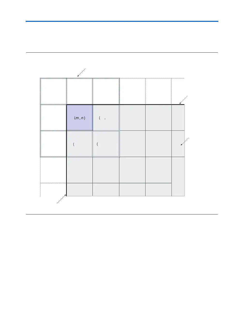
black pixels, that is pixels with value zero. This is similar to padding the
edges of the input image matrix with zeros and is referred to as the free
boundary condition. This is shown in Figure 7–27.
Figure 7–27. Using Free Boundary Condition for Edge Pixels
Convolution Implementation
This design example shows a 3 × 3 2-D FIR filter that takes in an 8 × 8
input image with gray pixel values ranging from 0-255 (8-bit). Data is fed
in serially starting from the top left pixel, moving horizontally on a row-
by-row basis. Next the data is stored in three separate RAM blocks in the
buffering stage. Each M512 memory block represents a line of the image,
and this is cycled through. For a 32 × 32 input image, the design needs
M4K memory blocks. For larger images (640
× 480), this can be extended
to M-RAM blocks or other buffering schemes. The control logic block
provides the RAM control signals to interleave the data across all three
1
1
1
1
x 3 kernel slides across ima
e
Image boundar
Ima
e
Image boundary