11–10 Altera Corporation
Stratix Device Handbook, Volume 2 July 2005
Configuration Schemes
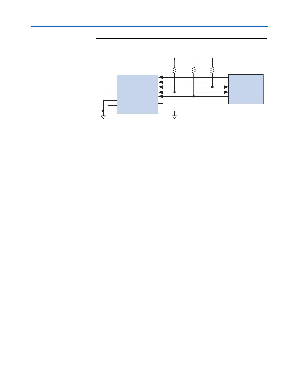
Figure 11–2. Single Device Configuration Circuit
Notes to Figure 11–2:
(1) The pull-up resistor should be connected to the same supply voltage as the
configuration device.
(2) The enhanced configuration devices and EPC2 devices have internal
programmable pull-ups on OE and nCS. You should only use the internal pull-ups
of the configuration device if the nSTATUS and CONF_DONE signals are pulled up
to 3.3 V or 2.5 V (not 1.8 V or 1.5 V). If external pull-ups are used, they should be
10 kΩ.
(3) The nINIT_CONF pin is available on EPC16, EPC8, EPC4, and EPC2 devices. If
nINIT_CONF is not used, nCONFIG must be pulled to V
CC
through a resistor. he
nINIT_CONF pin has an internal pull-up resistor that is always active in EPC16,
EPC8, EPC4, and EPC2 devices. These devices do not need an external pull-up
resistor on the nINIT_CONF pin.
Figure 11–3 shows how to configure multiple Stratix and Stratix GX
devices with multiple EPC2 or EPC1 configuration devices.
Stratix or Stratix GX Device
DCLK
DATA
OE
nCS
nINIT_CONF (3)
MSEL1
MSEL0
MSEL2
DCLK
DATA0
nSTATUS
CONF_DONE
nCONFIG
V
CC
V
CC
GND GND
(1)
(1)
nCE
V
CC
(1)
nCEO
N.C.
Configuration
Device
V
CC
10 kΩ
(2)
10 kΩ
(2)
(2)
(2)
10 kΩ
(3)