1–26 Altera Corporation
Stratix Device Handbook, Volume 2 July 2005
Enhanced PLLs
Spread-spectrum technology modulates the target frequency over a small
range. For example, if a 100-MHz signal has a 0.5% down-spread
modulation, then the frequency is swept from 99.5 to 100 MHz.
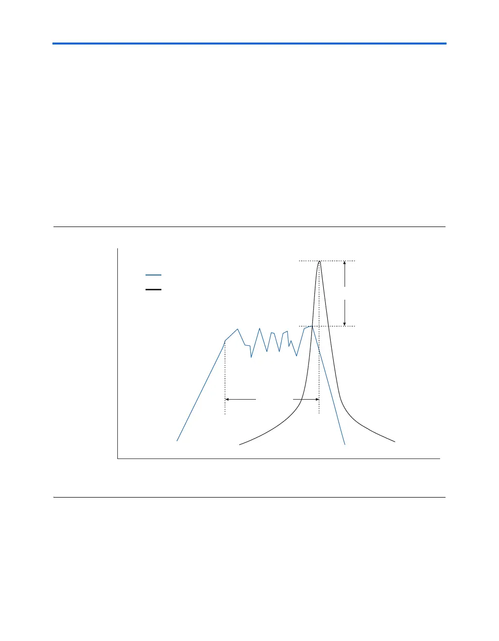
Figure 1–14 gives a graphical representation of the energy present in a
spread-spectrum signal as opposed to a non-spread-spectrum signal. It is
apparent that instead of concentrating the energy at the target frequency,
the energy is re-distributed across a wider band of frequencies, which
reduces peak energy.
Not only is there a reduction in the fundamental peak EMI components,
but there is also a reduction in EMI of the higher order harmonics. Since
some regulations focus on peak EMI emissions, rather than average EMI
emissions, spread-spectrum technology is a valuable method of EMI
reduction.
Figure 1–14. Spread-Spectrum Signal Energy versus Non-Spread-Spectrum Signal Energy
Spread-spectrum technology would benefit a design with high EMI
emissions and/or strict EMI requirements. Device-generated EMI is
dependent on frequency, output voltage swing amplitude, and slew rate.
For example, a design using LVDS already has low EMI emissions
δ = 0.5%
Δ = ~5 dB
Amplitude
(dB)
Frequency
(MHz)
Spread-Spectrum Signal
Non-Spread-Spectrum Signal