11–40 Altera Corporation
Stratix Device Handbook, Volume 2 July 2005
Configuration Schemes
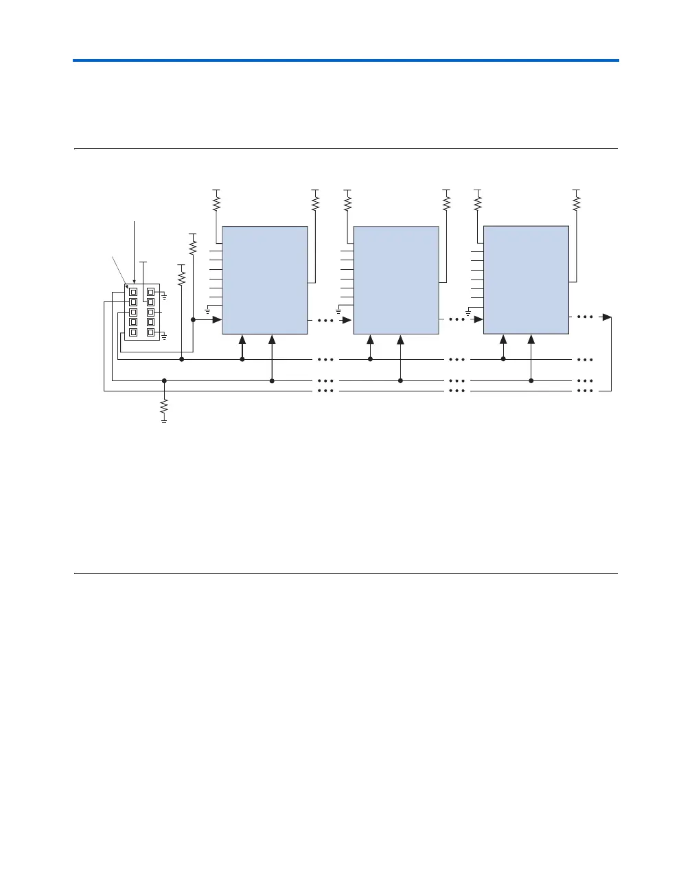
JTAG-chain device programming is ideal when the PCB contains multiple
devices, or when testing the PCB using JTAG BST circuitry. Figure 11–21
shows multi-device JTAG configuration.
Figure 11–21. Multi-Device JTAG Configuration Notes (1), (2)
Notes to Figure 11–21:
(1) Stratix, Stratix GX, APEX
TM
II, APEX 20K, Mercury
TM
, ACEX
®
1K, and FLEX
®
10K devices can be placed within the
same JTAG chain for device programming and configuration.
(2) For more information on all configuration pins connected in this mode, see Table 11–11 on page 11–37.
(3) Connect the nCONFIG, MSEL0, MSEL1, and MSEL2 pins to support a non-JTAG configuration scheme. If only JTAG
configuration is used, connect nCONFIG to V
CC
, and MSEL0, MSEL1, and MSEL2 to ground. Pull DATA0 and DCLK
to either high or low.
(4) V
IO
is a reference voltage for the MasterBlaster output driver. V
IO
should match the device’s V
CCIO
. See the
MasterBlaster Serial/USB Communications Cable Data Sheet for this value.
(5) nCE must be connected to GND or driven low for successful JTAG configuration.
The nCE pin must be connected to GND or driven low during JTAG
configuration. In multi-device PS, FPP and PPA configuration chains, the
first device's nCE pin is connected to GND while its nCEO pin is connected
to nCE of the next device in the chain. The last device's nCE input comes
from the previous device, while its nCEO pin is left floating. After the first
device completes configuration in a multi-device configuration chain, its
nCEO pin drives low to activate the second device's nCE pin, which
prompts the second device to begin configuration. Therefore, if these
devices are also in a JTAG chain, you should make sure the nCE pins are
connected to GND during JTAG configuration or that the devices are JTAG
configured in the same order as the configuration chain. As long as the
devices are JTAG configured in the same order as the multi-device
configuration chain, the nCEO of the previous device drives nCE of the
next device low when it has successfully been JTAG configured.
TMS TCK
MasterBlaster or ByteBlasterMV
10-Pin Male Header
TDI
TDO
VCC
V
CC
V
CC
Pin 1
nSTATUS
nCONFIG
MSEL2
MSEL1
nCE
V
CC
CONF_DONE
V
CC
TMS TCK
TDI
TDO
nCONFIG
MSEL2
MSEL1
nCE
V
CC
CONF_DONE
V
CC
TMS TCK
TDI
TDO
nCONFIG
MSEL2
MSEL1
nCE
V
CC
CONF_DONE
V
CC
1 kΩ
(3)
(3)
(3)
MSEL0
(3)
(3)
(3)
(3)
MSEL0
(3)
(3)
DCLK
DCLK
DCLK
(3)
(3)
(3)
DATA 0
DATA0
DATA0
(3)
(3)
(3)
(3)
(3)
MSEL0
(3)
VIO
(4)
Stratix Device Stratix Device Stratix Device
1 kΩ
nSTATUS nSTATUS
10 kΩ 10 kΩ 10 kΩ10 kΩ10 kΩ10 kΩ
(5)
(5)
(5)
1 kΩ