12–24 Altera Corporation
Stratix Device Handbook, Volume 2 September 2004
Using Enhanced Configuration Devices
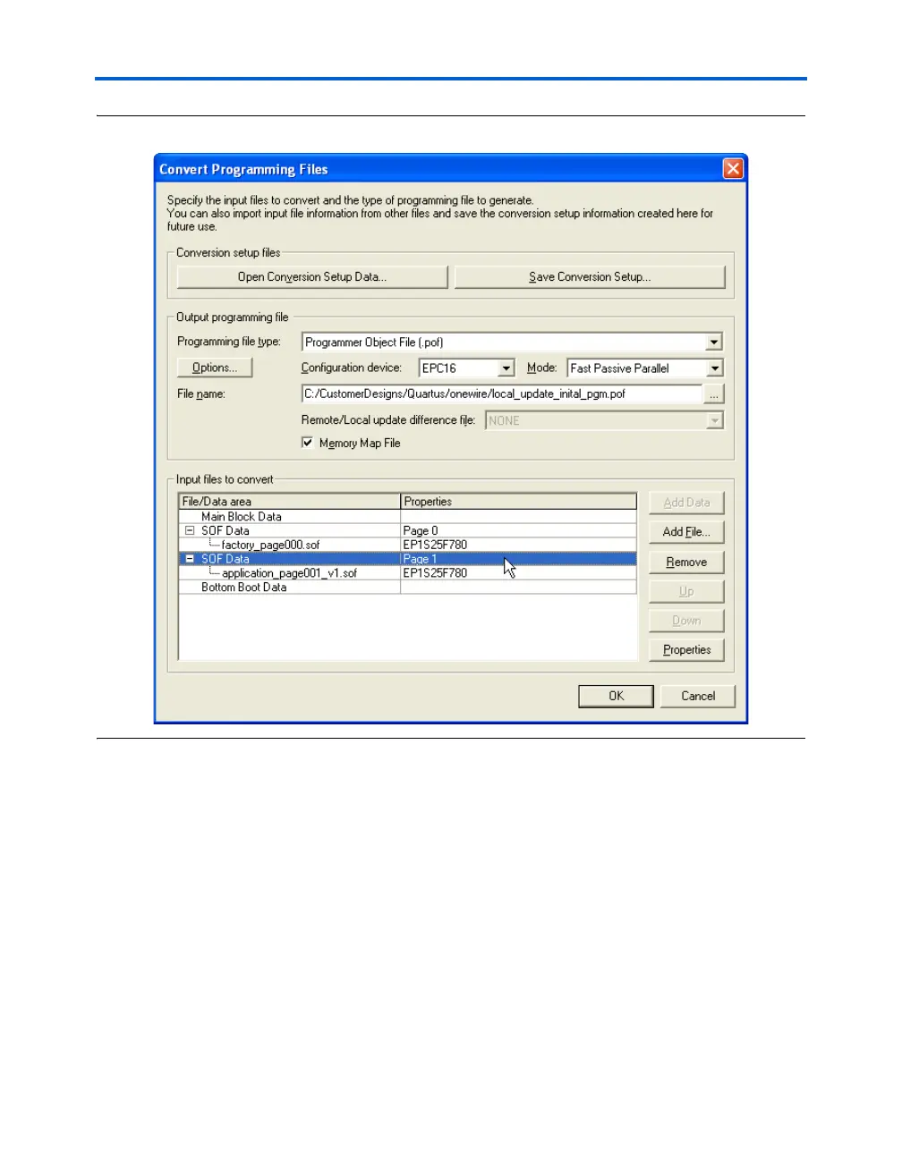
Figure 12–13. CPF Setup for Initial Programming File (Auto Addressing)
A sample memory map output file for the preceding setup is shown
below. Configuration option bits and page 0 data occupy main flash
sectors 0 through 4. See the Sharp LHF16J06 Flash memory used in EPC16
devices Data Sheet at www.altera.com to correlate memory addresses to
the EPC16 flash sectors. In auto addressing mode, page 1 allocates all
unused flash sectors. For this example, this unused area includes main
sectors 5 through 30, and all of the bottom boot sectors. While this large
portion of memory is allocated for page 1, the real application
configuration data is top justified within this region with filler 1'b1 bits in
lower memory addresses. Notice that the page 1 configuration data