12–38 Altera Corporation
Stratix Device Handbook, Volume 2 September 2004
Using Enhanced Configuration Devices
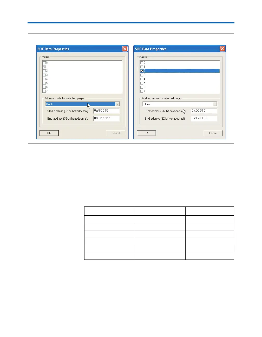
Figure 12–21. Specifying Block Addresses for an Application Configuration
A sample memory map output file for the preceding example is shown
below. Note that the allocated memory for page 1 is between
0x00070000 and 0x000BFFFF, while the actual region used by the
current application configuration bitstream is between 0x0007B144 and
0x000BFFFF. The configuration data is top justified within the allocated
SOF data region. Similarly, the allocated memory for page 2 is between
0x000D0000 and 0x0012FFFF, while the actual region used by the
application configuration is between 0x000EB13E and 0x0012FFF9.
Also note that the HEX data stored in the main data area uses absolute
addressing. If relative addressing were to be used, the main data contents
would be justified with the top (higher address locations) of the memory.
The initial POF can be converted to an Intel Hexadecimal format file
(*.HEXOUT) using the Quartus II CPF utility. See Figure 12–22.
Block Start Address End Address
BOTTOM BOOT 0x00000000 0x000001FF
OPTION BITS 0x00010000 0x0001003F
PAGE 0 0x00010040 0x00054EFA
PAGE 1 0x0007B144 0x000BFFFF
PAGE 2 0x000EB13E 0x0012FFF9
TOP BOOT/MAIN 0x001F0000 0x001F01FF