Altera Corporation 14–13
January 2005 Stratix Device Handbook, Volume 2
Designing with 1.5-V Devices
Figure 14–10. LT1085: 5.0-V-to-1.5-V/3-A Linear Voltage Regulator
Note to Figure 14–10:
(1) This capacitor is necessary to maintain the voltage level at the input regulator.
There could be a voltage drop at the input if the voltage supply is too far away.
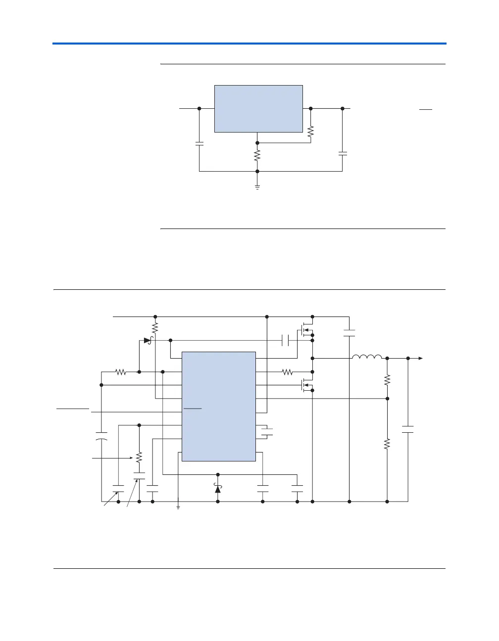
Figure 14–11 shows a high-efficiency switching regulator circuit diagram.
A selectable resistor network controls the output voltage. The resistor
values in Figure 14–11 are selected for 1.5-V output operation.
Figure 14–11. LT1649: 3.3-V-to-1.5-V/15-A Asynchronous Switching Regulator
Notes to Figure 14–11:
(1) MBR0530 is a Motorola device.
(2) IRF7801 is a International Rectifier device.
(3) See the Panasonic 12TS-1R2HL device.
LT1084
ADJ
OUTIN
C
1
V
IN
+
C
2
+
R1
5 k
Ω
R2
1 k
Ω
10 μF
10 μF
(1)
V
OUT
= 1.25 V × (1 + )
R
2
R
1
P
VCC1
P
VCC2
V
CC
I
MAX
SHDN
COMP
SS
GND
G1
I
FB
G2
FB
V
IN
C
+
C
–
CP
OUT
LTC1649
+
+
+
+
0.33 μF10 μF
1 μF
1 μF
1 kΩ
MBR05300.1 μF
10 μF
22 kΩ
R
IMAX
50 kΩ
R
1
2.16 kΩ
R
2
12.7 kΩ
C
OUT
4,400 μF
V
OUT
1.5 V
(15 A)
SHUTDOWN
MBR0530 (1)
Q3
IRF7801
R
C
7.5 kΩ
C
C
0.01 μF
C
1
220 pF
Q1, Q2
IRF7801
Two in
Parallel (2)
C
IN
3,300 μF
V
IN
3.3 V
L
EXT
(3) 1.2 μH