2. Technical System Description 1/2010 2 - 10
BA-TE-DE08C M.KAY
Dialog+ SW9xx_sm_Chapter 2_1-2010.doc/pdf <100329> yymmdd
B. Braun Avitum AG
Dialog
+
SW 9.xx
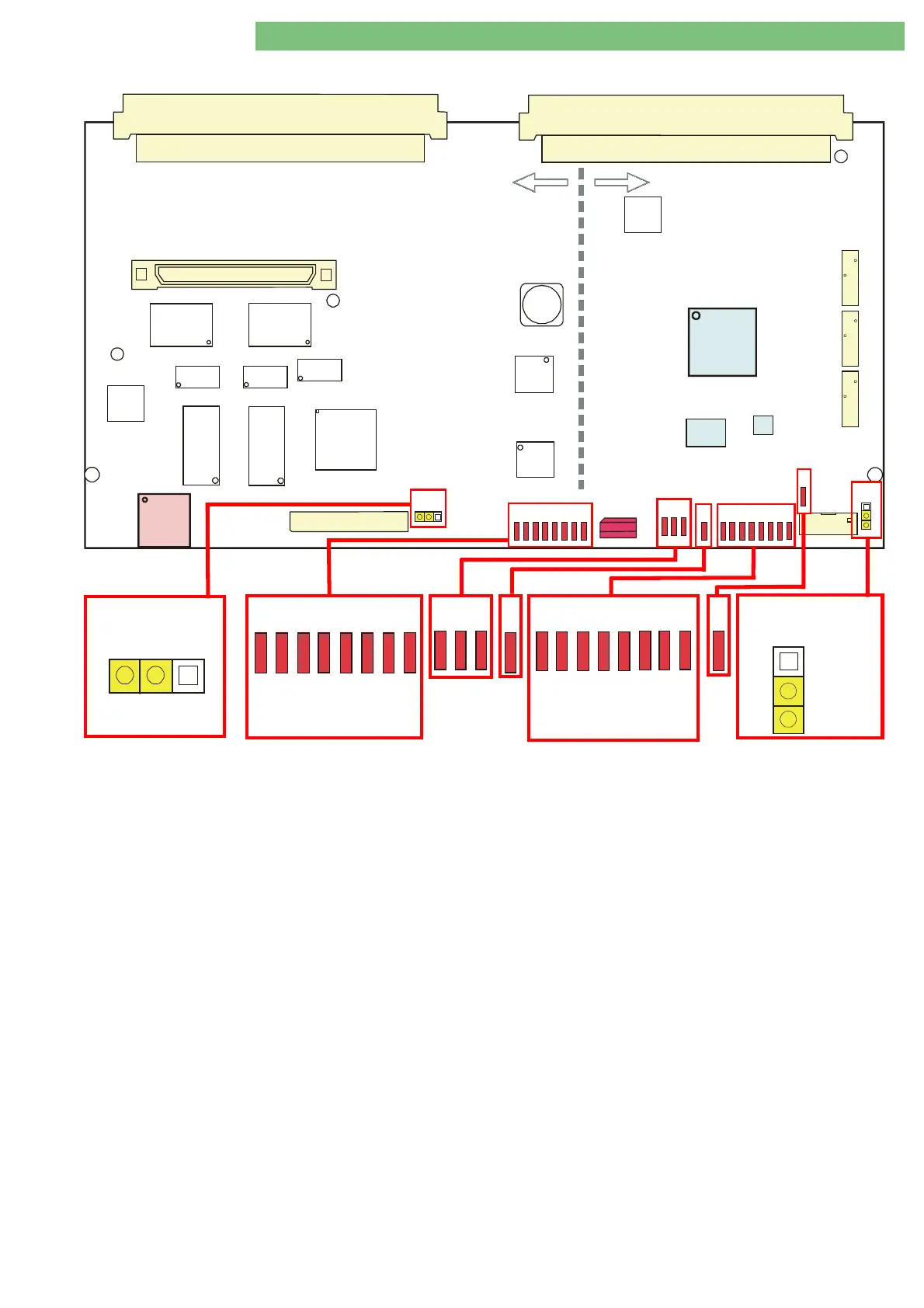
2.6 Digital Board DB
P2
P1
P4
S1
P14
P11
P13
JP1
JP2
U56
U55
U43
U39
U35
U36
U33
U28
U53
L33
U30
FPGA
P7
P6
P5
U7
U27
U45
Controller
Supervisor
U46
S1
D16
D27
D24
D17
D25
D18
D28
D26
D19
D29
D20
D30
D21
D31
D22
D32
D34
D23
D33
D35
D13
Fig. : Digital Board DB (LLD) with Controller and Supervisor
2.6.1 Legend Digital Board
Calibration Data
All calibration data are stored on the digital board. The
calibration data must be stored additionally on the compact flash
card CFC.
12 Bit AD Converter
Both supervisor and controller have a 12 bit AD converter with a
range of 0 to 4095.
P4/P5/P6/P7/P13/P14
: not applicable
P11
USB Type A for SW installation with USB stick
Supervisor Sensors:
BICPOS, KPPOS, UFPOS
Controller/Supervisor Sensors:
BKUS, SBS1, SBS2, BPS_IMP, BPA_DIR, BPV_IMP, BPV_DIR
Pumps:
BPA, BPV, EP, FPA, FPE
Controller Sensors:
NSVB, BICSS, KSS, MSBK1/2, RDV, SAD, BPADS, BPVDS,
BL (Controller/Supervisor Sensor Analog Board)
Jumper JP1:
Jumper JP1:Jumper JP1:
Jumper JP1:
Default: Controller Write Protect CWP (for controller firmware)
Controller LEDs D13 – D20:
Controller LEDs D13 – D20:Controller LEDs D13 – D20:
Controller LEDs D13 – D20:
Status 0 – 7 for installation of LLC software
FPGA LEDs V7 – V9
FPGA LEDs V7 – V9FPGA LEDs V7 – V9
FPGA LEDs V7 – V9: always ON
Voltages for FPGA (U30) and periphery
(FPGA: Field Programmable Gate Array – configurable logical circuit)
LED V10
LED V10LED V10
LED V10: flashes permanently
Cycle time, system is running
Supervisor LEDs V11 – V18
Supervisor LEDs V11 – V18Supervisor LEDs V11 – V18
Supervisor LEDs V11 – V18:
Status 0 – 7 for installation of LLS software
LED V5
LED V5LED V5
LED V5: always ON after loading
The content of the memory (U45) is loaded to FPGA (U30) during
switch-on. The therapy program and the service program is stored
in the RAM (U45).
Jumper JP2:
Jumper JP2:Jumper JP2:
Jumper JP2:
Default: Supervisor Write Protect SWP (for supervisor firmware)
S1 Service Switch:
Position 0:
Therapy Mode
Position 2:
TSM Service Program Mode
Position 3:
Software Installation/Update Mode
D16
D17
D18
D19
D20
D21
D22
D23
01234
5
6
7
Controller
D28
D29
D30
D31
D32
D34
D33
D35
01234567
Supervisor
D24
D25
D26
D27
D13
JP1
CWP
SWP
JP2