ECG Monitoring
8-28
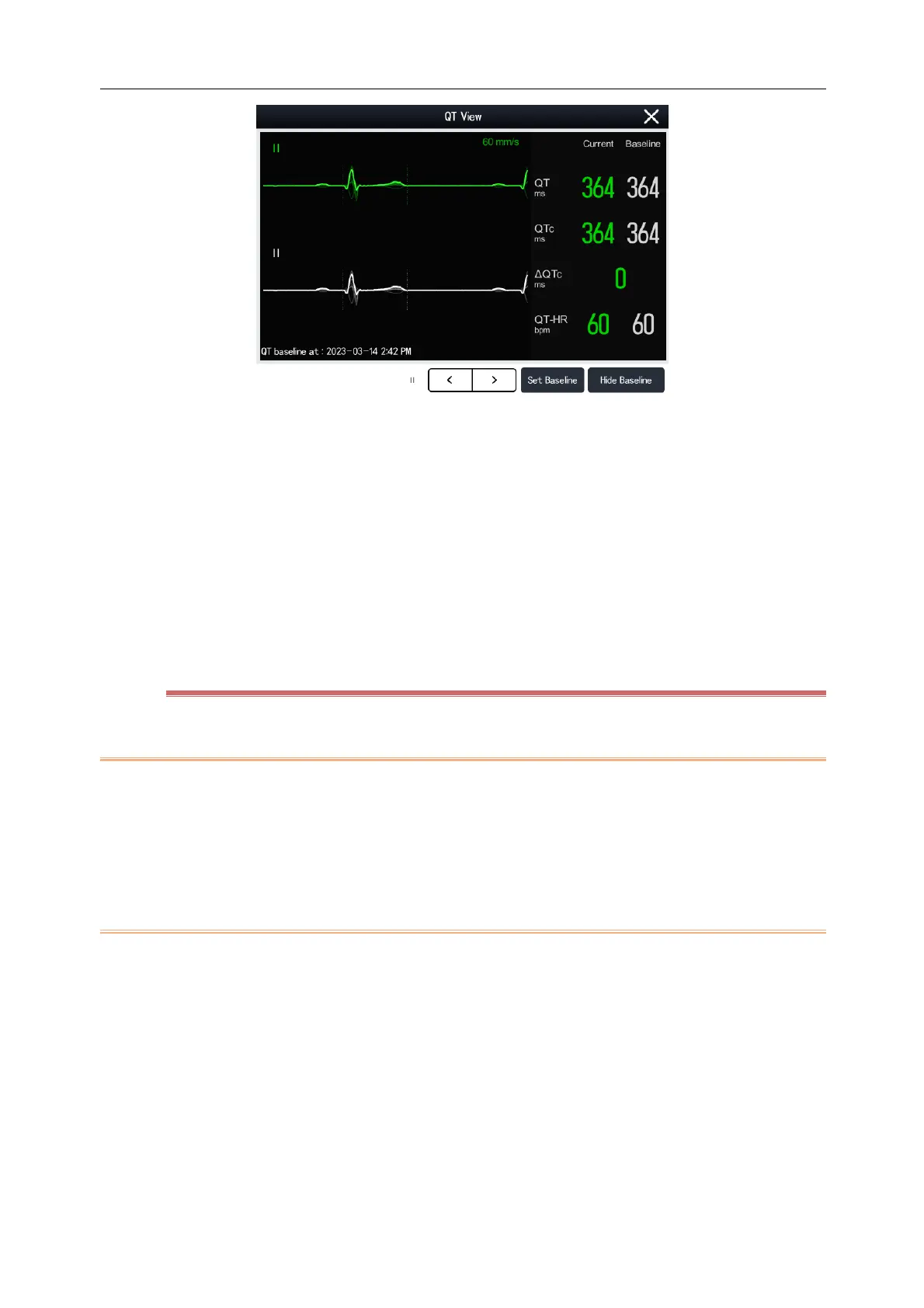
The current waveform is displayed at the top of the QT View screen in the same color (usually green) as the
ECG waveform.
The baseline segment is displayed below and in white color.
The location of QRS complex and T wave end point is marked with vertical lines.
In some cases, the QT measurements results cannot be displayed because of poor signal quality. In this case,
the reasons of analysis failureis are displayed below the QT parameter area, and the message “QT Analysis
Failed” is appear in alarm message area of the main screen display.
Select the left and right arrows below to switch leads and highlight the waveform of the corresponding lead.
8.8.5 QT Setup
8.8.5.1 QT Alarm
1) Select the QT parameter area, ECG parameter area or ECG waveform area to enter [ECG] menu.
2) Select [QT] tab.
3) Set the QTc and ΔQTc alarms in the [Alarm] page.
8.8.5.2 QT Leads
You can select one or all of the available leads as QT leads. Steps to select QT leads are as follows:
1) Select the QT parameter area, ECG parameter area or ECG waveform area to enter [ECG] menu.
2) Select [QT] tab.
3) Select [Setup] tab.
4) Set [QT Leads]. The default is [All], that is, all leads are selected as QT leads.