Overview
2-7
call signal will be activated to alert the nurse if an alarm is generated.
May be used as the synchronization defibrillation output port to output defibrillation
synchronization signals.
May be used as the analog output port to output analog signals.
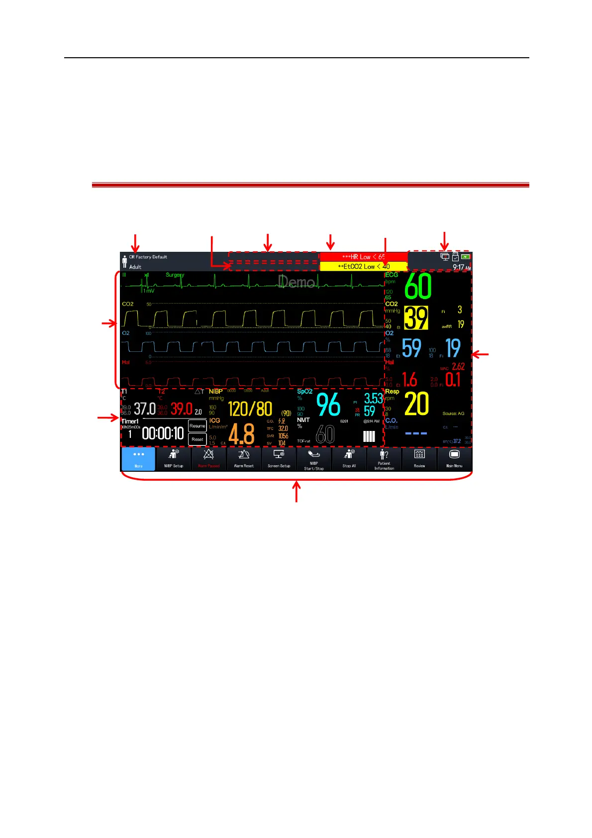
2.3 On-screen Display (OSD)
The figure below shows a general interface:
(1). Patient Information Area: Displays patient information, including department, current configuration, patient
type, etc. Select this area to enter the [Patient Management] menu. See
“Section 5 Patient Management”
for
details.
(2). Prompt Message Area: Displays prompt messages.
(3). Technical Alarm Message Area: Displays technical alarm messages.
(4). High Level Physiological Alarm Message Area: Displays high level physiological alarm messages.
(5). Medium and Low Level Physiological Alarm Message Area: Displays medium and low level physiological alarm
messages.
(6). System Status Information Area: Displays alarm icon, battery icon, network, connection status of storage device,
and system time. See
“Section 2.6.1 Interface Symbols”
for details.
(7). Parameter Area: Displays parameter values, units, alarm limits, alarm states, etc.. The user can select a
parameter area to enter the corresponding parameter setup menu. See
“Section 4.3.1 Enter the Parameter
Setup Window”
for details.
(8). Hot Key Area: Displays hot keys.