RESP Monitoring
10-2
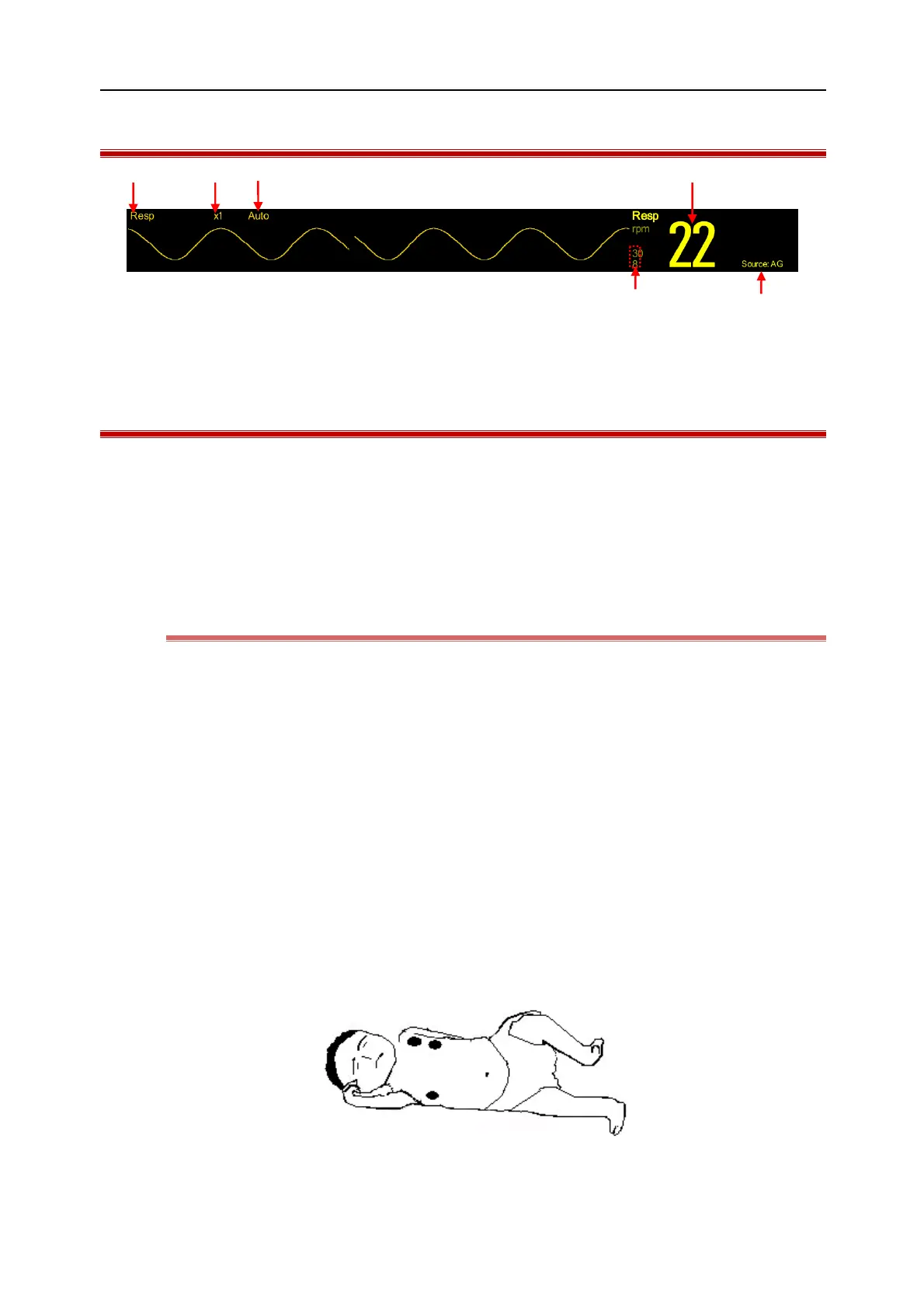
10.3 Resp Display
(1) Parameter (2) Waveform gain (3)Lead label
(4) Respiration Rate(RR) (5) RR source (6) RR alarm limit
10.4 Placement of Electrodes
In Resp measurement it is important to prepare the skin properly for electrode placement. Refer to the ECG
measurement section or relevant information.
The Resp signals are measured through the two ECG electrodes. When the ECG electrodes are placed in standard
position the Resp can be measured through the electrode RA and electrode LL.
10.4.1 Optimization of Lead Position
To measure the ECG and Resp simultaneously it may be necessary to adjust the positions of the two electrodes for
some patients. Non-standard placement of ECG electrodes may cause changes to the ECG waveform and affect the
ST segment analysis and ARR analysis.
1) Cardiovascular Artifact
The cardiac activities affecting the Resp waveform are defined as cardiovascular artifact, which accurs when the
electrodes collect the impedance changes caused by rhythmatic blood flow. Proper placement of electrodes can
reduce cardiovascular artifact. Avoid the liver area and ventricles to be in the line between the electrodes, which is
especially important to neonates.
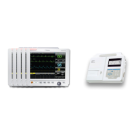
2) Lateral Thoracic Expansion
The thoracic cage of some patients, especially neonates, may expand to both sides. To obtain the best Resp
waveform place the two electrodes respectively at the right mid-axillary line and left outer chest with strongest
Resp movements, as shown below:
3) Abdominal Respiration