CO
2
Monitoring
15-8
15.5.2.4 Preparations for Comen Sidestream CO
2
Module (other than plug-in module)
1) Insert the CO
2
module to the monitor's CO
2
interface.
2) Wait for 2min until the sensor reaches its working temperature and a stable thermal state.
3) Insert the sampling line into the interface of the CO
2
sensor securely until you hear a "click" sound.
4) Zero the sensor; please refer to "
Section15.6 Zeroing the CO
2
Sensor
" for more information.
5) Set CO
2
parameters; please refer to "
Section15.7 CO
2
Setup
" for more information.
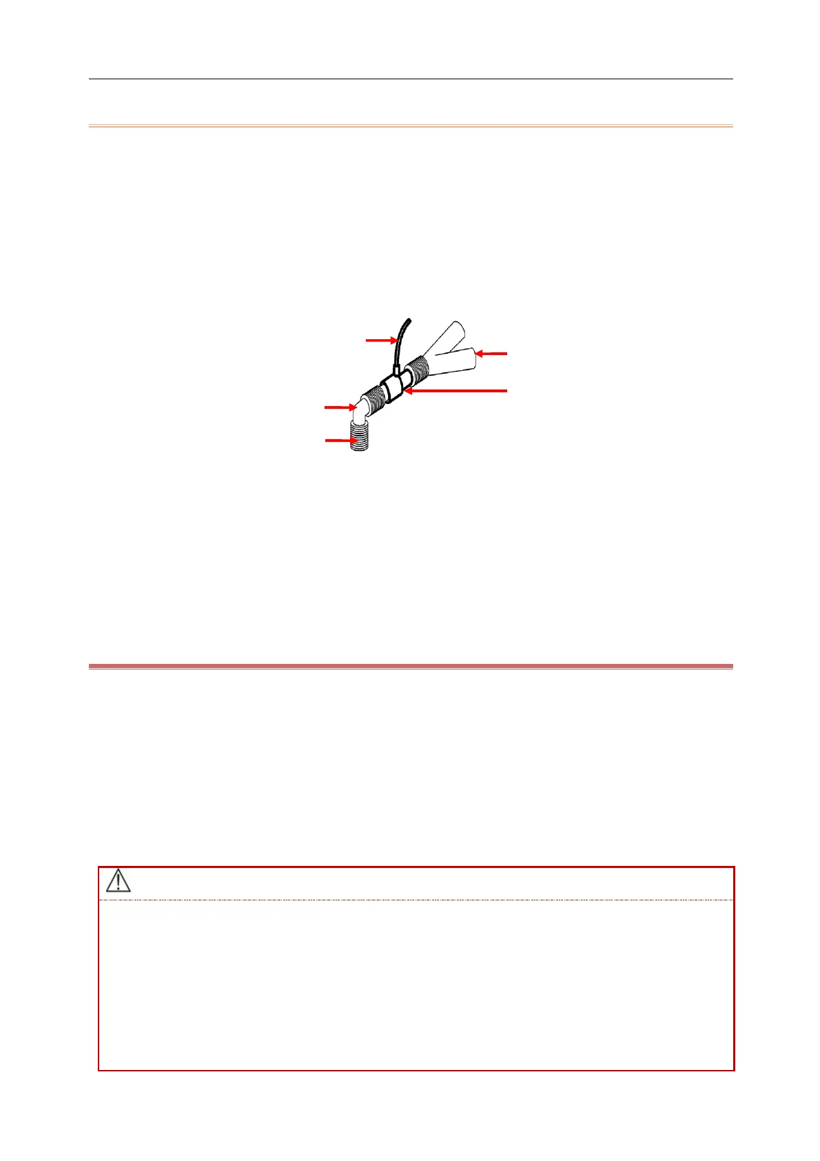
6) For the patient with tracheal cannula: install the airway adapter of the sampling line onto one end of the
respiration circuit, such as between the elbow tube and the Y-shaped tube, shown as the figure below:
(1) Sampling line (2) Y-shaped tube (3) Airway adapter (4) Respiration circuit port (5) Elbow tube
7) Placement of the nasal cannula for the patient without tracheal cannula: place the nasal cannula onto the
patient's face.
8) Connect an exhaust pipe to the vent on the sensor so as to exhaust waste gases into the waste gas treatment
system.
9) Start the measurement after confirming the airway tightness.
15.5.3 Checks before Use for Masimo CO
2
Module
Perform the following operations before connecting the Nomoline sampling tube to the respiration circuit:
1) Connect the sampling tube to the gas inlet of the ISA CO
2
module.
2) Check if the LED remains a steady green (an indication of a normal system).
3) Exhale into the sampling tube and check if the monitor displays an effective CO
2
waveform and value.
4) Block the sampling tube with a fingertip and wait for 10s.
5) Check if the prompt message “Sampling line clogged” appears and the LED flashes red.
6) Check the tightness of the patient circuit connected to the sampling tube when appropriate.
Securely hang the external CO
2
analyzer onto the CO
2
holder on the back housing of the monitor so it
does not fall and become damaged.
Unless HME is used to protect the IRMA sensor, the LED state indicator should face upwards all the time
during IRMA sensor placement.
Do not pull the cable of the ISA sidestream gas analyzer.
Do not operate the ISA sidestream Gas Analyzer in an environment beyond the designated operating
temperature.
Make sure all connections are firm and reliable. Any leakage will result in the inclusion of ambient air in