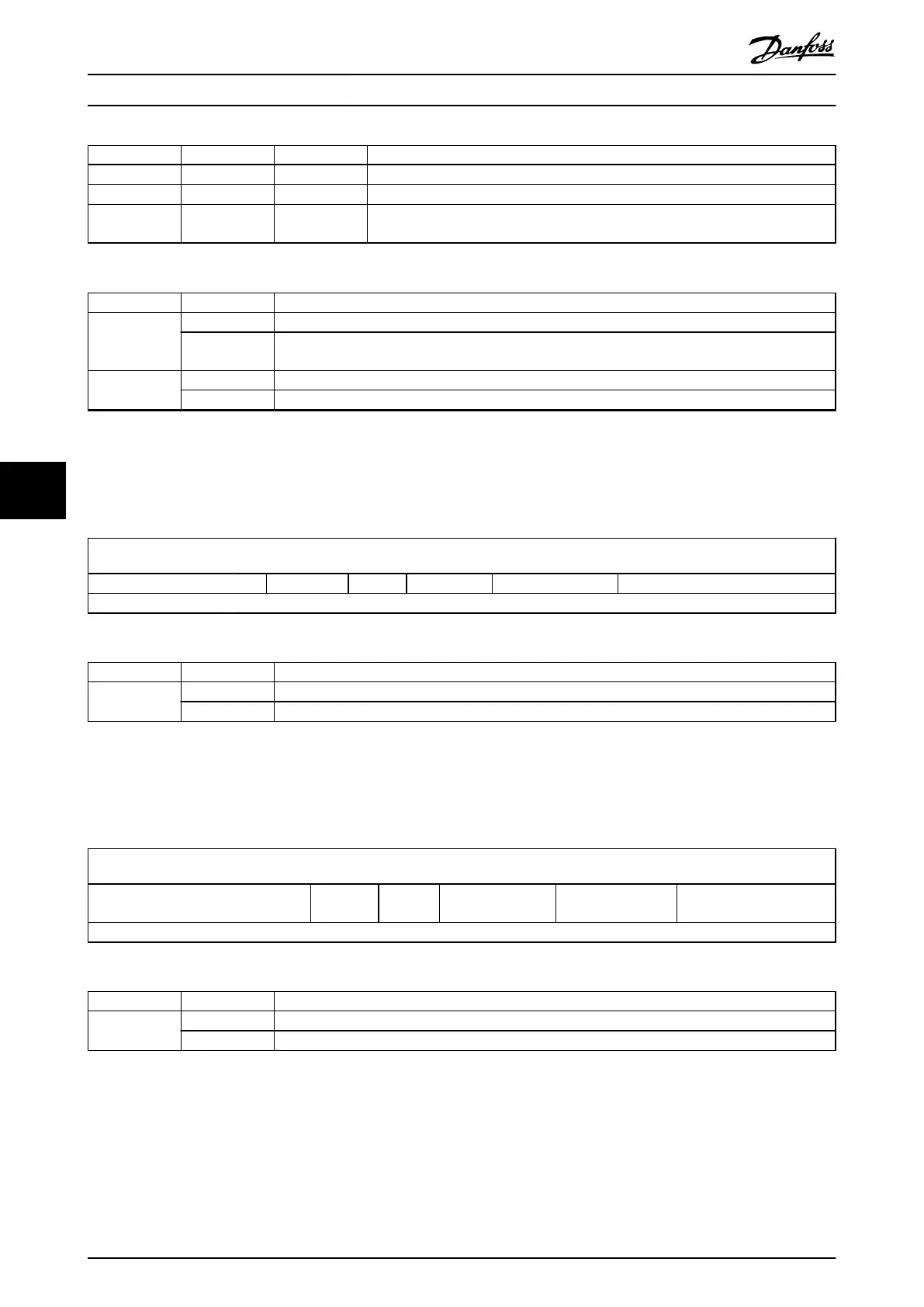
Bit 9 Bit 5 Bit 4 Denition
0 0
0 → 1
Positioning is completed (target reached) before the next one is started.
X (= don’t care) 1
0 → 1
Next positioning is started immediately.
1 0
0 → 1
Positioning with the current prole velocity is carried out up to the current setpoint
and then the next positioning is applied.
Table 7.7 Denition of Bits 4, 5, and 9
Bit Value Denition
6 0 Target position is an absolute value.
1 Target position is a relative value depending on object 0x60F2 (see chapter 7.10.3 Parameter: Positioning
Option Code (0x60F2)).
8 0 The motion is executed or continued.
1 Stop axis according to halt option code (see chapter 7.20.7 Parameter 50-47: Halt Option Code (0x605D)).
Table 7.8 Denition of Bits 6 and 8
7.2.1.2 Controlword in Prole Velocity Mode
Table 7.9 shows the structure of the Controlword. Table 7.10 denes the values for bit 8 of the Controlword.
15
10 9 8 7 6 4 3 0
See Table 7.2 Reserved (0) Halt See Table 7.2 Reserved (0) See Table 7.2
MSB LSB
Table 7.9 Controlword for Prole Velocity Mode
Bit Value Denition
8 0 The motion is executed or continued.
1 Stop axis according to halt option code (see chapter 7.20.7 Parameter 50-47: Halt Option Code (0x605D)).
Table 7.10 Denition of Bit 8
7.2.1.3 Controlword in Prole Torque Mode
Table 7.11 shows the structure of the Controlword. Table 7.12 denes the values for bit 8 of the Controlword.
15
10 9 8 7 6 4 3 0
See Table 7.2
Reserved
(0)
Halt See Table 7.2 Reserved (0) See Table 7.2
MSB LSB
Table 7.11 Controlword for Prole Torque Mode
Bit Value Denition
8 0 The motion is executed or continued.
1 Stop axis according to halt option code (see chapter 7.20.7 Parameter 50-47: Halt Option Code (0x605D)).
Table 7.12 Denition of Bit 8
Servo Drive Parameter Descr...
VLT
®
Integrated Servo Drive ISD
®
510 System
234 Danfoss A/S © 01/2017 All rights reserved. MG36D102
77

 Loading...


