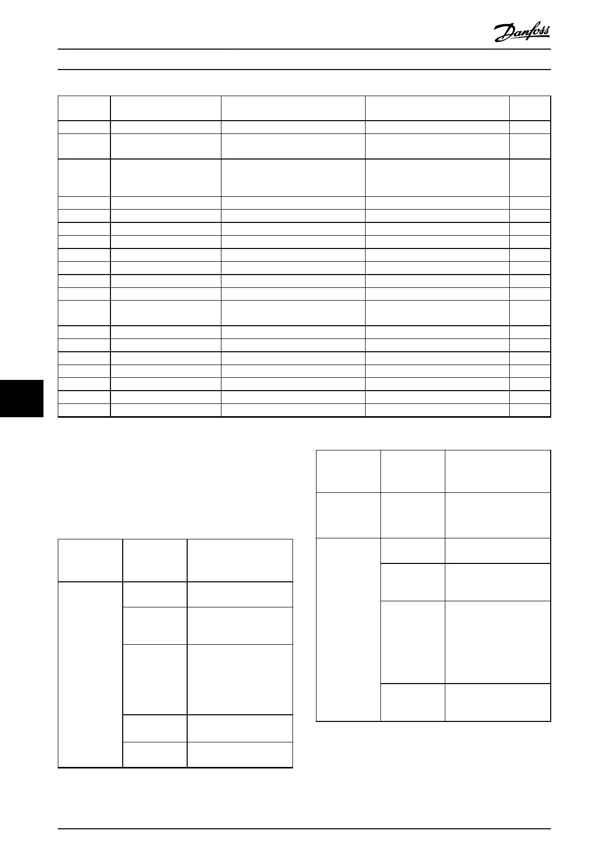
Signal ID
(hex)
Signal name PLC library -
trace constant name
Description OD object
80000008 Rotor position logical ISD51x_TRC_ROTOR_POS_ACT_VIRT Logical rotation position of motor shaft –
80000009 Following error ISD51x_TRC_PCTRL_LAG_ERROR Following error (dierence between act
value and setpoint)
–
8000000A Rotor mech angle raw ISD51x_TRC_ROTOR_POS_RAW Raw mechanical angle, not
compensated for resolver mounting to
pole, not mirrored
–
8000000B Rotor speed relative – Rotor speed relative –
8000000E Position ctrl set ISD51x_TRC_PCTRL_POS_SET Setpoint of position control loop –
8000000F Logical CAM setpoint ISD51x_TRC_CAM_POS_SET Position setpoint in cam mode 0x2021
80000010 Cam velocity set ISD51x_TRC_CAM_N_SET Speed setpoint in cam mode –
80000012 Controlword ISD51x_TRC_CONTROLWORD Controlword 0x6040
80000013 Statusword ISD51x_TRC_STATUSWORD Statusword 0x6041
80000014 Motion and input status ISD51x_TRC_MOTION_AND_INPUT Motion and input status 0x2006
80000015 Cam prole status ISD51x_TRC_CAM_PROFILE_STATUS Cam prole status 0x3085
80000016 Logical CAM setpoint scaled – Position setpoint in cam mode after
slave scaling
–
80000017 CAM friction torque ISD51x_TRC_CAM_FRICTION_COMP Cam friction compensation torque –
80000020 Position actual value ISD51x_TRC_POSITION_ACTUAL_VALUE Actual position in user-dened units 0x6064
80000021 Velocity actual value ISD51x_TRC_DS402_VELOCITY_ACT_VAL Actual velocity in user-dened units 0x606C
80000022 Torque actual value ISD51x_TRC_TORQUE_ACTUAL_VALUE Actual torque ‰ of rated torque 0x6077
80000023 Following error actual value ISD51x_TRC_DS402_FOLLOW_ERR Following error in user-dened units 0x60F4
80000025 Position guide value reference ISD51x_TRC_GUIDE_REF_VAL_POS Position guide value reference 0x2062
80000026 Velocity guide value reference ISD51x_TRC_GUIDE_REF_VAL_SPEED Velocity guide value reference 0x2065
Table 9.3 Trace Signals for Servo Drive
9.3
SAB
9.3.1 Troubleshooting
Table 9.4 lists potential faults on the SAB, their possible
causes, and actions for correcting the faults.
Fault Possible cause Possible solution
LCP display dark
or has no
function.
Missing input
power.
Check the input power
source.
Missing or open
fuses or circuit
breaker tripped.
Check the fuses and circuit
breaker.
No power to the
LCP.
•
Check the LCP cable for
proper connection or
damage.
•
Replace any faulty LCP
or connection cables.
Incorrect
contrast setting.
Press [Status] + [
▲
]/[
▼
] to
adjust the contrast.
Display is
defective.
Replace the faulty LCP or
connection cable.
Fault Possible cause Possible solution
Open power
fuses or circuit
breaker trip.
Phase-to-phase
short.
•
Check the cabling.
•
Check for loose
connections.
DC-link voltage
too high.
Brake resistor
not connected.
Check the brake resistor
cabling.
Brake resistor
too high
resistance.
Check if the lowest
resistance value has been
entered.
Several servo
drives are
decelerating
with insucient
ramp time.
•
Avoid simultaneous
deceleration of several
servo drives.
•
Change the deceleration
speed of the servo
drives.
Brake resistor
functionality not
activated.
Activate the brake function.
Diagnostics
VLT
®
Integrated Servo Drive ISD
®
510 System
372 Danfoss A/S © 01/2017 All rights reserved. MG36D102
99

 Loading...


