Enumeration MC_SYNC_MODE_ISD51x denes the synchro-
nization types for the gear in process.
Name Description
mcShortest_ISD51x Synchronization is done to have the
shortest way for the slave.
mcCatchUp_ISD51x Synchronization is done to catch up to
the master axis (synchronization to current
master cycle).
mcSlowDown_ISD51x Synchronization is done to slow down to
the master axis (synchronization 1 master
cycle later).
Table 6.50 Enumeration MC_SYNC_MODE_ISD51x
6.5.5.11 DD_GetInertia_ISD51x
This function block is used to determine the inertia of the
servo drive system. Only activate the function block when
the axis is in state Standstill. Only values >0 are allowed for
the inputs VelocityLimit and TorqueLimit.
The command is transferred and executed immediately.
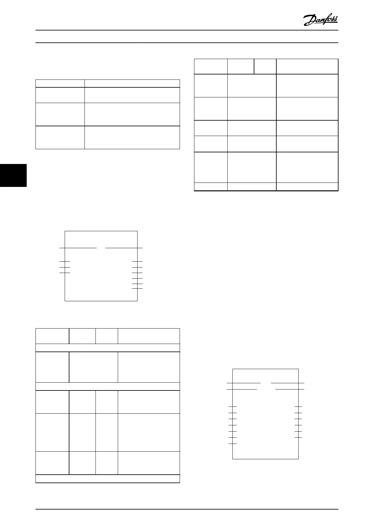
DD_GetInertia_ISD51x
Axis
ExecuteBOOL
AXIS_REF_-
ISD51x
VelocityLimitUDINT
TorqueLimitUINT
BOOLDone
BOOLBusy
BOOLError
BOOLCommandAborted
DD_ERROR_ISD51xErrorInfo
REALInertia
130BE264.10
Illustration 6.71 DD_GetInertia_ISD51x
Variable
name
Data type Default
value
Description
VAR_IN_OUT
Axis AXIS_REF_ISD51x Reference to the axis.
See
chapter 6.5.4.1 AXIS_REF_IS
D51x.
VAR_INPUT
Execute BOOL FALSE Starts the inertia
measurement at rising
edge.
VelocityLimit UDINT 0 Maximum velocity used
during the measurement
[user-dened velocity unit].
Only values >0 are
allowed.
TorqueLimit UINT 0xFFFF Maximum torque used
during this motion [mNm
(Millinewtonmeter)].
VAR_OUTPUT
Variable
name
Data type Default
value
Description
Done BOOL The inertia measurement
has completed successfully
and the value is available.
Busy BOOL The function block is not
nished and new output
values are to be expected.
CommandA-
borted
BOOL Command is aborted by
another command.
Error BOOL An error has occurred
within the function block.
ErrorInfo DD_ERROR_ISD51x Error identication and
instance identier.
See chapter 6.5.2.3 Error
Indication.
Inertia REAL Measured inertia [kg m²].
Table 6.51 DD_GetInertia_ISD51x
6.5.6 Drive – CAM Operation
6.5.6.1 MC_CamTableSelect_ISD51x
This function block selects the CAM tables by setting the
connections to the relevant tables. When the Done output
is set, the axis internal buer dened by CamTableID is
valid and ready for use in a MC_CamIn_ISD51x function
block. The sending and parsing of the CAM can take some
time.
The function block sends the information to the axis.
Execute this function block for every axis if >1 axis must
follow the same CAM. This function block only writes the
CAM information to the servo drive and does not activate
the CAM. Use function block MC_CamIn_ISD51x to activate
the CAM. If the CAM prole contains a pattern alignment,
the pattern le must be given to input PatternFile. If there
is no pattern alignment inside the CAM, use an empty
string.
MC_CamTableSelect_ISD51x
Slave
ExecuteBOOL
AXIS_REF_ISD51x
CamTable
STRING(80)
BOOLDone
BOOLBusy
DD_ERROR_ISD51xErrorinfo
BOOL
WORDParseError
DWORDParseErrorDebug
Error
CamTableIDUSINT
SlaveAbsoluteBOOL
CyclicBOOL
PathE_OpenPath
PatternFileSTRING(80)
MasterAbsoluteBOOL
Illustration 6.72 MC_CamTableSelect_ISD51x in TwinCAT
®
Programming
VLT
®
Integrated Servo Drive ISD
®
510 System
212 Danfoss A/S © 01/2017 All rights reserved. MG36D102
6
6

 Loading...


