9.4 Operating Status Indicators
The operating status of the servo drive and SAB is
indicated via the LEDs on each device.
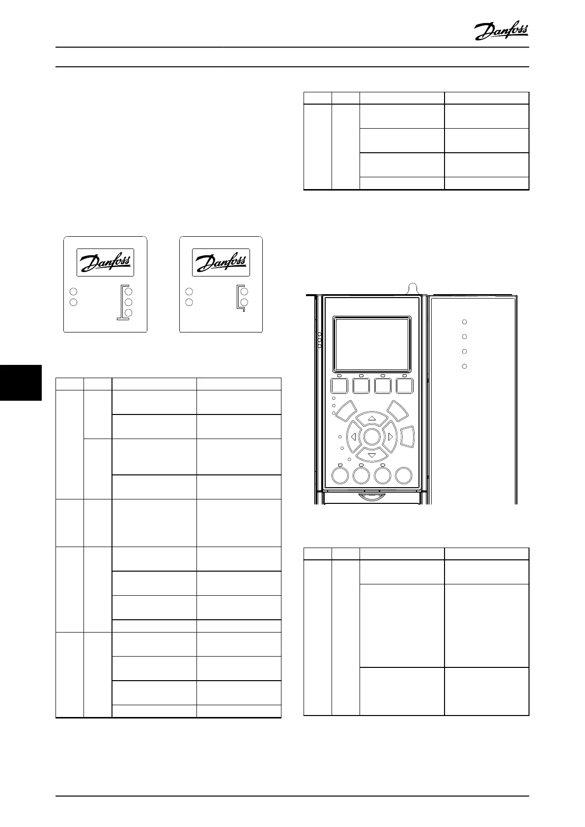
9.4.1 Operating LEDs on the Servo Drive
Illustration 9.1 shows the operating LEDs on the servo
drive.
DRIVE STAT X1
X2
X3
NET STAT
LINK/ACT
DRIVE STAT X1
X2NET STAT
LINK/ACT
Advanced Standard
130BE677.10
Illustration 9.1 Operating LEDs on the Servo Drive
LED Color Flash status Description
DRIVE
STAT
Green On Servo drive is in state
Operation enabled.
Flashing Auxiliary voltage is
applied.
Red On Servo drive is in Fault
or Fault reaction active
state.
Flashing DC-link voltage is not
applied.
NET
STAT
Green/
red
Fieldbus dependent Network status of the
device (see
corresponding eldbus
standard).
Link/A
CT X1
Green – Link/activity status of
Hybrid In (X1)
On Ethernet link
established.
Flashing Ethernet link
established and active.
O No link.
Link/A
CT X2
Green – Link/activity status of
Hybrid Out (X2)
On Ethernet link
established.
Flashing Ethernet link
established and active.
O No link.
LED Color Flash status Description
Link/A
CT
X3
1)
Green – Link/activity status of
the Ethernet port (X3).
On Ethernet link
established.
Flashing Ethernet link
established and active.
O No link.
Table 9.7 Legend to Illustration 9.1
1) Advanced version only
9.4.2 Operating LEDs on the Servo Access
Box
Aux 1
Aux 2
Safe 1
Safe 2
130BE733.10
Illustration 9.2 Operating LEDs on the SAB
LED Color Flash status Description
Aux 1 Green – State of the auxiliary
voltage on line 1.
On State machine is in
state Standby, Power
up, or Operation
enabled. Auxiliary
voltage is applied to
the output connectors
on line 1.
O State machine is in
state U
AUX
disabled or
Fault. Auxiliary voltage
is not applied to line 1.
Diagnostics
VLT
®
Integrated Servo Drive ISD
®
510 System
378 Danfoss A/S © 01/2017 All rights reserved. MG36D102
99

 Loading...


