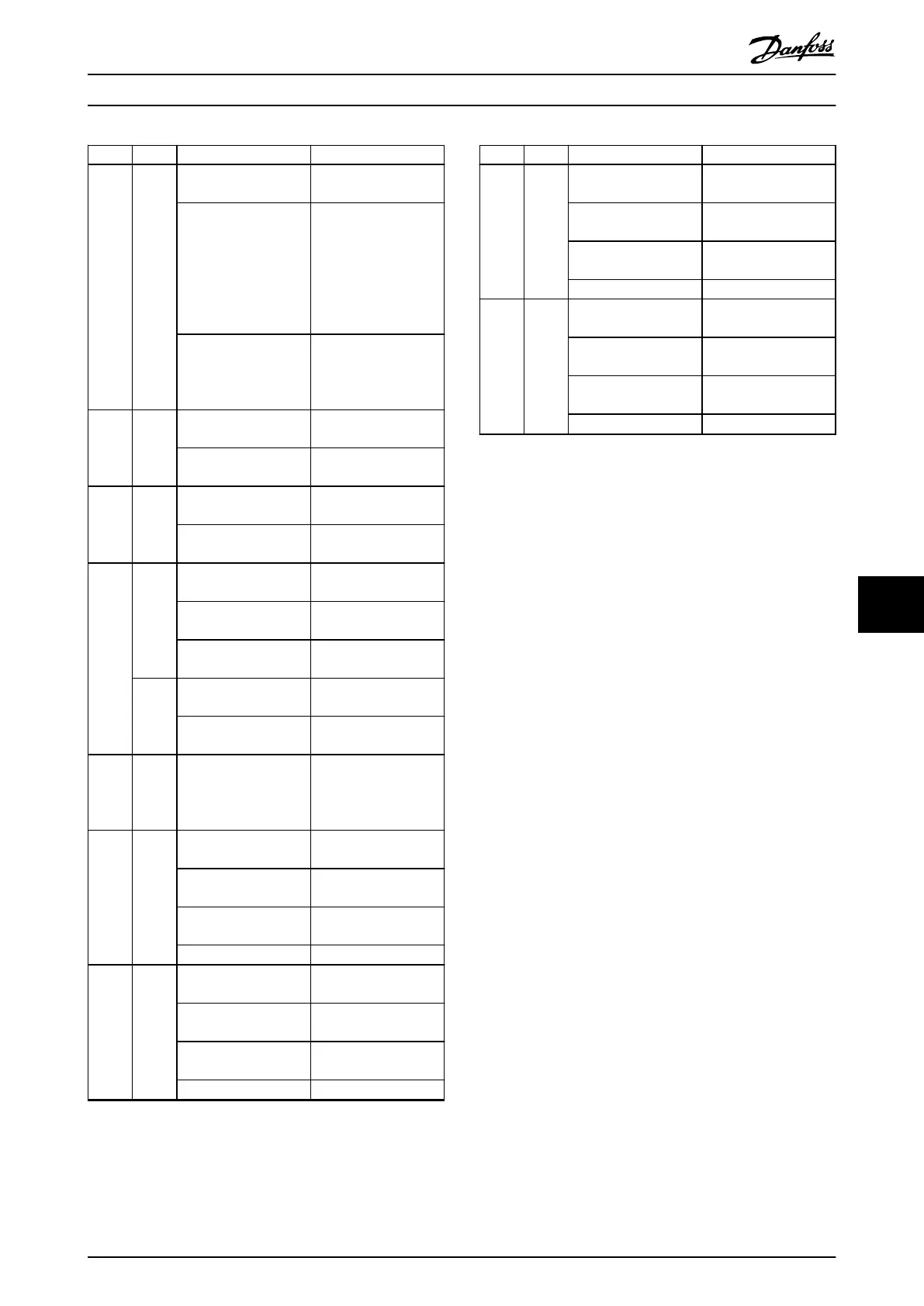
LED Color Flash status Description
Aux 2 Green – State of the auxiliary
voltage on line 2.
On State machine is in
state Standby, Power
up, or Operation
enabled. Auxiliary
voltage is applied to
the output connectors
on line 2.
O State machine is in
state U
AUX
disabled or
Fault. Auxiliary voltage
is not applied to line 2.
Safe 1 Green On 24 V for STO is present
on line 1.
O 24 V for STO is not
present on line 1.
Safe 2 Green On 24 V for STO is present
on line 2.
O 24 V for STO is not
present on line 2.
SAB
STAT
Green On SAB is in state
Operation enabled.
Flashing Auxiliary voltage is
applied at the input.
O No auxiliary voltage is
applied at the input.
Red On The SAB is in state
Fault.
Flashing Mains is not applied at
the input.
NET
STAT
Green/
red
Fieldbus dependent. Network status of the
device (see
corresponding eldbus
standard).
Link/A
CT X1
Green – Link/activity status of
In.
On Ethernet link
established.
Flashing Ethernet link
established and active.
O No link.
Link/A
CT X2
Green – Link/activity status of
Out.
On Ethernet link
established.
Flashing Ethernet link
established and active.
O No link.
LED Color Flash status Description
Link/A
CT X3
Green – Link/activity status of
line 1.
On Ethernet link
established.
Flashing Ethernet link
established and active.
O No link.
Link/A
CT X4
Green – Link/activity status of
line 2.
On Ethernet link
established.
Flashing Ethernet link
established and active.
O No link.
Table 9.8 Legend to Illustration 9.2
Diagnostics Programming Guide
MG36D102 Danfoss A/S © 01/2017 All rights reserved. 379
9 9

 Loading...


