Bit Value Denition
13 0 No following error.
1 Following error.
Table 7.37 Denition of Bits 10, 12, and 13
NOTICE
Bit 13: Refer to chapter 2.7.3 Following Error Detection for more information about the following error detection.
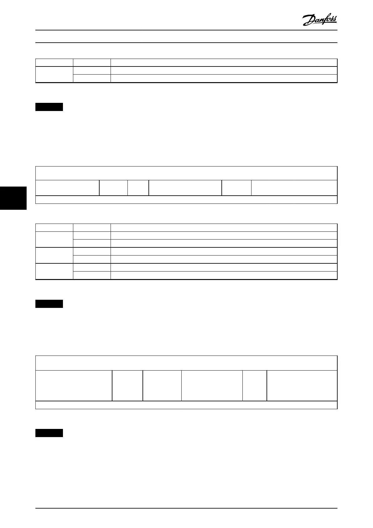
7.3.1.7 Statusword in ISD Inertia Measurement Mode
The ISD Inertia Measurement Mode uses some bits of the Statusword for operation mode-specic purpose. Table 7.38 shows
the structure of the Statusword. Table 7.39 denes the values for bits 10, 12, and 13.
15
14 13 12 11 10 9 0
See Table 7.23.
Measureme
nt error
Standstil
l
See Table 7.23.
Target
reached
See Table 7.23.
MSB LSB
Table 7.38 Statusword in ISD Inertia Measurement Mode
Bit Value Denition
10 0 Result of measurement is not available.
1 Measurement has nished and result can be read.
12 0 Velocity is not 0 (measurement is ongoing or the servo drive is coasting).
1 Velocity is 0.
13 0 No error in measurement.
1 Error occurred during measurement.
Table 7.39 Denition of Bits 10, 12, and 13
NOTICE
Bit 13: The error reason can be read from object 0x2009 (see chapter 7.16.1 Parameter 52-60: Measured Inertia (0x2009)).
7.3.1.8 Statusword in Cyclic Synchronous Position Mode
Table 7.40 shows the structure of the Statusword.
15
14 13 12 11 10 9 0
See Table 7.23
Following
error
Servo drive
follows the
commanded
value
See Table 7.23
Status
toggle
See Table 7.23
MSB LSB
Table 7.40 Statusword in Cyclic Synchronous Position Mode
NOTICE
Bit 10: Used as status toggle information to indicate if the device provides updated input data. The bit is toggled with
every update of the input process data.
Bit 12: Is 0 if the servo drive does not follow the target value because of local control. Bit 12 is set if the servo drive is
in state Operation enabled and follows the target and setpoint values of the control device. In all other cases, it is 0.
Bit 13: The following error bit. The following error value is only evaluated in state Operation enabled. After a reset, the
setpoint is set to the actual value so that the following error is 0.
Servo Drive Parameter Descr...
VLT
®
Integrated Servo Drive ISD
®
510 System
242 Danfoss A/S © 01/2017 All rights reserved. MG36D102
77

 Loading...


