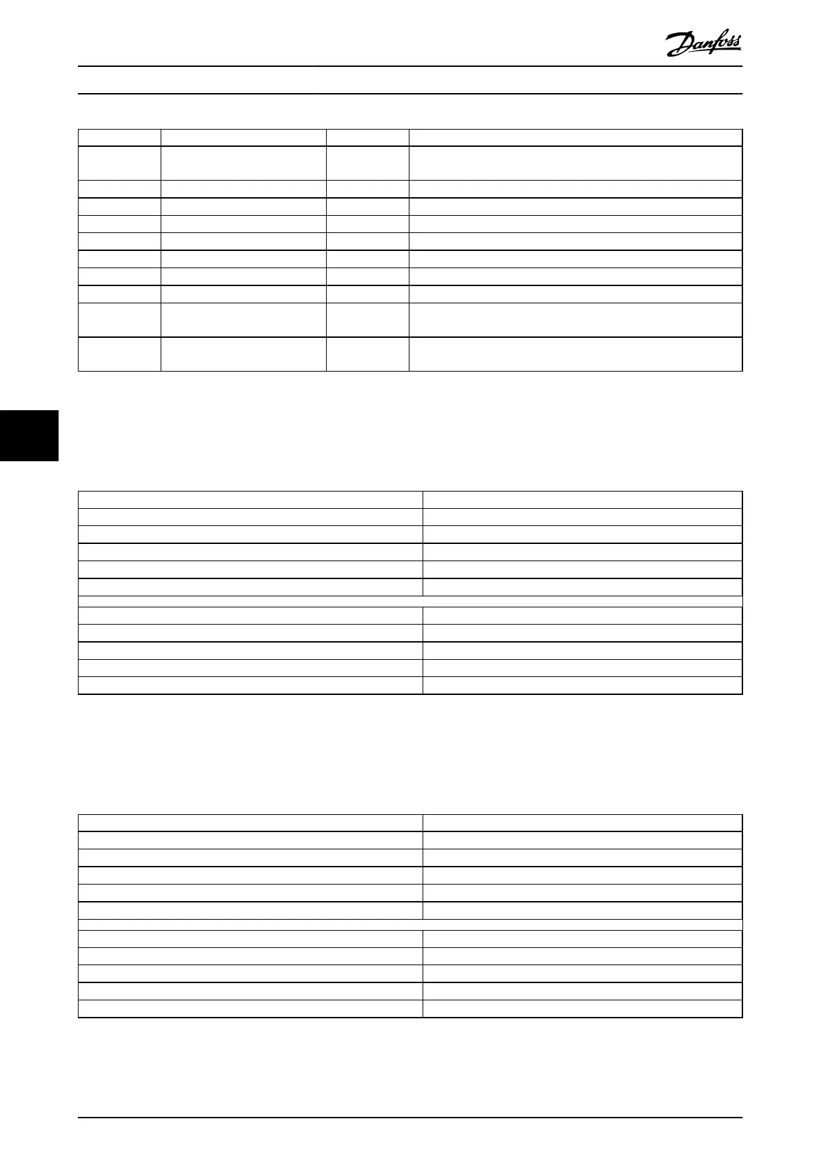
Value Denition Abbreviation Control
–7 = 0xF9 Gear mode gr Position controlled (can be velocity controlled during synchroni-
zation phase).
–6 = 0xFA CAM mode cam Position controlled
–5 = 0xFB ISD Inertia measurement mode im Torque controlled
0 No mode change – –
+1 Prole position mode pp Position controlled
+3 Prole velocity mode pv Velocity controlled
+4 Torque prole mode tq Torque controlled
+6 Homing mode hm Velocity controlled
+8 Cyclic synchronous position
mode
csp Position controlled
+9 Cyclic synchronous velocity
mode
csv Velocity controlled
Table 7.48 Supported Modes of Operation
7.5.2 Parameter 52-01: Modes of Operation Display (0x6061)
This object provides the actual operation mode.
Attribute Value
Index 0x6061
LCP parameter number 52-01
Name Modes of operation display
Object code Var
Data type INTEGER8
Sub-index 0x00
Access Read only
PDO mapping Optional
Value range See Table 7.48.
Default value 1
Table 7.49 0x6061: Modes of Operation Display
7.5.3 Parameter: Supported Drive Modes (0x6502)
This object provides information on the supported drive modes.
Attribute Value
Index 0x6502
LCP parameter number –
Name Supported drive modes
Object code Var
Data type UNSIGNED32
Sub-index 0x00
Access Read only
PDO mapping Optional
Value range See Table 7.51.
Default value Dependent on rmware version.
Table 7.50 0x6502: Supported Drive Modes
Servo Drive Parameter Descr...
VLT
®
Integrated Servo Drive ISD
®
510 System
248 Danfoss A/S © 01/2017 All rights reserved. MG36D102
77

 Loading...


