ms Manufacturer-specic
r Reserved
oms Operation mode specic
h Halt
fr Fault reset
eo Enable operation
qs Quick stop
ev Enable voltage
so Switch on
cs Control set selection
do Set/reset the digital output
dcs Digital CAM switching functionality enabled/disabled
Table 7.3 Denition of Controlword Bits
Bit Value Denition
11 0 Digital CAM switching functionality must be disabled (see chapter 2.5.1 Digital CAM Switch).
1 Digital CAM switching functionality must be enabled (see chapter 2.5.1 Digital CAM Switch).
12 0 Digital output is cleared.
1 Digital output is set.
15 0 Control parameter set 1 is used (objects 0x2012 and 0x2013; see chapter 2.3.6 Control Loops).
1 Control parameter set 2 is used (objects 0x2014 and 0x2015; see chapter 2.3.6 Control Loops).
Table 7.4 Manufacturer-specic Bits in Controlword
Command
Controlword bits
Transitions
Bit 7 Bit 3 Bit 2 Bit 1 Bit 0
Shutdown 0
X
1)
1 1 0 2, 6, 8
Switch on 0 0 1 1 1 3
Switch on and enable operation 0 1 1 1 1
3, 4
2)
Disable voltage 0
X
1)
X
1)
0
X
1)
7, 9, 10, 12
Quick stop 0
X
1)
0 1
X
1)
7, 10, 11
Disable operation 0 0 1 1 1 5
Enable operation 0 1 1 1 1 4, 16
Fault reset
0→1
X
1)
X
1)
X
1)
X
1)
15
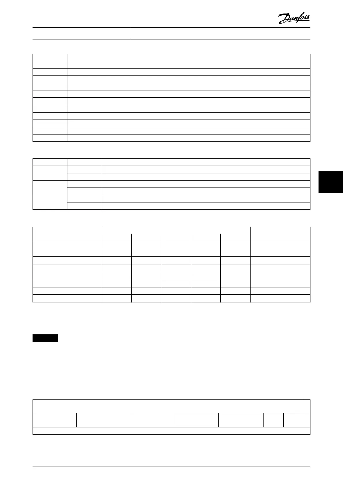
Table 7.5 Command Coding
1) X denotes Don’t care.
2) Automatic transition to Enable operation state after executing Switched on state functionality.
NOTICE
See chapter 2.3.1 State Machine for the relevant transitions.
7.2.1.1 Controlword in Prole Position Mode
Table 7.6 shows the structure of the Controlword. Table 7.7 denes the values for bit 4, 5 and 9 of the Controlword. Table 7.8
denes the values for bit 6 and 8 of the Controlword. If no positioning is in progress, the rising edge of bit 4 starts the
positioning of the axis. If positioning is in progress, the values given in Table 7.7 dene the behavior.
15
10 9 8 7 6 5 4 3 0
See Table 7.2
Change on
setpoint
Halt See Table 7.2 Abs/rel
Change set
immediately
New
setpoint
See
Table 7.2
MSB LSB
Table 7.6 Controlword for Prole Position Mode
Servo Drive Parameter Descr... Programming Guide
MG36D102 Danfoss A/S © 01/2017 All rights reserved. 233
7 7

 Loading...


