the servo drive, which performs velocity control and
torque control.
Velocity
control
Torque
control
M
s
Target velocity (0x60FF)
Torque actual value (0x6077)
Velocity actual value (0x606C)
Position actual value (0x6064)
Illustration 2.118 Cyclic Synchronous Velocity Mode Overview
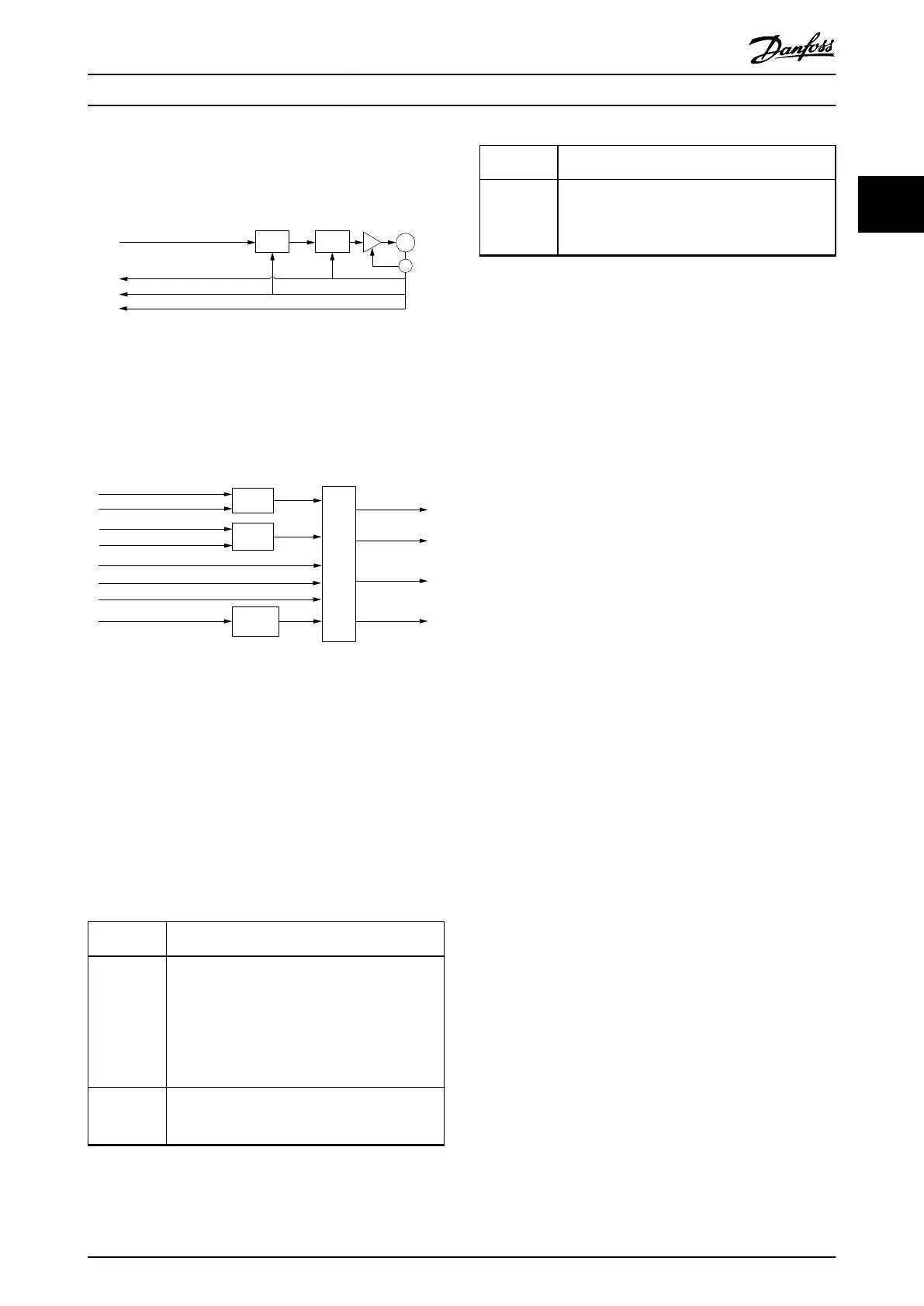
Illustration 2.119 shows the inputs and outputs of the servo
drive control function. The input value (from the control
function point of view) is the target velocity.
130BF264.10
Drive
control
function
Multiplier
Multiplier
Minimum
comparator
Target
velocity
Target velocity (0x60FF)
Torque
limit
Position actual
value (0x6064)
Velocity actual
value (0x606C)
Torque actual
value (0x6077)
Following error
actual value
(0x60F4)
Max torque (0x6072)
Drive mirror mode (0x2016,02)
Drive mirror mode (0x2016,02)
Max motor speed (0x6080)
Quick-stop deceleration (0x6085)
Quick-stop option code (0x605A)
Interpolation time period (0x60C2)
Illustration 2.119 Cyclic Synchronous Velocity Control Function
The servo drive supports limitation of motor speed and a
quick stop function for emergency reasons. The torque is
limited as well. The interpolation time period denes the
time period between 2 updates of the target velocity
and/or additive velocity and is used for intercycle interpo-
lation. The position actual value is used as mandatory
output to the control device. The PLC calculates the actual
velocity from the changes to the actual position changes.
All values are given in user-dened units.
2.5
Motion Functions
Function Description
Digital CAM
switch
This functionality controls whether the digital
output is enabled or disabled, depending on the
axis position. It performs a function comparable
to switches on a motor shaft. Forward and
backward movements of the axis position are
allowed. On and o compensation and hysteresis
can be parameterized.
ISD touch
probe
This functionality stores the position actual value
at a rising or falling edge of the congured digital
input.
Function Description
Guide value The guide value is used in all synchronous modes
of operation (CAM mode and Gear mode). It is
used as the master position within the
synchronous modes.
Table 2.57 Motion Functions
2.5.1 Digital CAM Switch
This functionality controls whether the digital output is
enabled or disabled, depending on the axis position. It
performs a function comparable to switches on a motor
shaft. Forward and backward movements of the axis
position are allowed. On and o compensation and
hysteresis can be parameterized.
The digital CAM switches are stored and handed over to
the servo drive using the contents of an XML le. The
content is stored automatically in the servo drive. There is
only 1 conguration for the digital CAM switches and a
maximum of 100 switches are supported.
The calculation of the digital CAM switches is based on the
Position actual value (see chapter 7.7.5 Parameter 50-03:
Position Actual Value (0x6064)) in all modes of operation
except CAM mode. In CAM mode, the calculation is based
on the Logical CAM position (see chapter 7.14.12 Parameter:
Logical CAM Position (0x2020)). The cyclic usage of switches
is based on the range of the Position actual value and/or
the Logical CAM position.
Information about the state of the digital CAM switching
functionality is given in object 0x2005 (see
chapter 7.22.13 Parameter 50-07: Overlaying Motion Status
(0x2005)).
A compensation time with which the switching on (see
chapter 7.17.1 Parameter: On Compensation (0x3840)) or the
switching
o (see chapter 7.17.2 Parameter: O Compen-
sation (0x3841)) can be advanced or delayed in time.
A hysteresis can be dened by using object 0x3842 (see
chapter 7.17.3 Parameter: Hysteresis (0x3842)) to avoid
jittering around the switching point.
To use the digital CAM switch, transfer the le content to
object 0x3844 (see chapter 7.17.5 Parameter: Digital CAM
Switches Data (0x3844)). Afterwards, parse the prole using
object 0x3843 (see chapter 7.17.4 Parameters: Digital CAM
Switch Parsing Control (0x3843)). When the status signals
that the data is valid, the functionality can be enabled by
using the Controlword (see chapter 7.2.1 Parameter 16-00
Controlword (0x6040)).
Servo Drive Operation Programming Guide
MG36D102 Danfoss A/S © 01/2017 All rights reserved. 79
2 2

 Loading...


