chapter 6.5.5.11 DD_GetInertia_ISD51x). It can also be used
via LCP parameter 52-6* Inertia Measurement. The
measured inertia is written to object 0x2009 (see
chapter 7.16.1 Parameter 52-60: Measured Inertia (0x2009)).
The measured value is not automatically used by the
control loop.
WARNING
DANGER OF MOVING PARTS
The servo drive moves during the measurement.
•
Limit the maximum velocity to be used during
measurement using object 0x200A, sub-index
01 (see chapter 7.16.2 Parameters 52-61 and
52-62: Inertia Measurement Parameters (0x200A)).
•
Limit the maximum torque to be used during
measurement using object 0x200A, sub-index
02 (see chapter 7.16.2 Parameters 52-61 and
52-62: Inertia Measurement Parameters (0x200A)).
To start the measurement, the servo drive must be
switched to ISD Inertia Measurement mode. Switching is
always possible when the servo drive is disabled. If the
servo drive is in state Operation enabled, it must be in
Standstill (dened in chapter 10.1 Glossary). Start the
measurement by using bit 4 in the Controlword (see
chapter 7.2.1 Parameter 16-00 Controlword (0x6040)). The
end of the measurement is reported in the Statusword (see
chapter 7.3.1 Parameter 16-03 Statusword (0x6041)). After
the measurement, the value can be read from object
0x2009 (see chapter 7.16.1 Parameter 52-60: Measured
Inertia (0x2009)).
If an error occurred during the measurement, the servo
drive signals the error in the Statusword and the value of
object 0x2009 (see chapter 7.16.1 Parameter 52-60:
Measured Inertia (0x2009)) is used for the error reason.
2.4.8 Cyclic Synchronous Position Mode
In Cyclic synchronous position mode, the trajectory
generator of the position is located in the control device,
not in the servo drive. The overall structure for this mode
is shown in Illustration 2.116. The servo drive provides
actual values for position, velocity, and torque to the
control device. In cyclic synchronous manner, it provides a
target position to the servo drive, which performs position
control, velocity control, and torque control.
Position
control
Velocity
control
Torque
control
M
s
Target position (0x607A)
Torque actual value (0x6077)
Velocity actual value (0x606C)
Position actual value (0x6064)
Illustration 2.116 Cyclic Synchronous Position Mode Overview
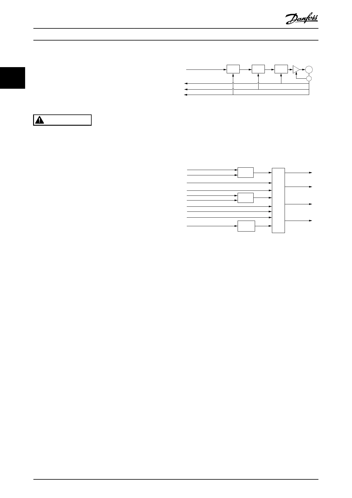
Illustration 2.116 shows the inputs and outputs of the servo
drive control function. The input value (from the control
function point of view) is the target position.
130BF262.10
Drive
control
function
Multiplier
Multiplier
Minimum
comparator
Target
position
Target position (0x607A)
Torque
limit
Position actual
value (0x6064)
Velocity actual
value (0x606C)
Torque actual
value (0x6077)
Following error
actual value
(0x60F4)
Max torque (0x6072)
Drive mirror mode (0x2016,02)
Drive mirror mode (0x2016,02)
Following error window (0x6065)
Following error time out (0x6066)
Max motor speed (0x6080)
Quick-stop deceleration (0x6085)
Quick-stop option code (0x605A)
Interpolation time period (0x60C2)
Illustration 2.117 Cyclic Synchronous Position Control Function
The servo drive monitors the following error. Other
features specied in this mode are limitation of motor
speed and a quick stop function for emergency reasons.
The torque is limited as well. The interpolation time period
denes the time period between 2 updates of the target
position and is used for intercycle interpolation.
The target position is interpreted as absolute value. The
position actual value is used as output to the control
device. Further outputs are the velocity actual value,
torque actual value, and the following error actual value.
All values are given in user-dened units.
A target position value outside the allowed range of the
following error window around a position demand value for
longer than the following error time-out results in setting
bit 13 (Following error) in the Statusword to 1. Object
0x2055: Following error option code is not supported in
this mode of operation.
2.4.9 Cyclic Synchronous Velocity Mode
In Cyclic synchronous velocity mode, the trajectory generator
of the velocity is located in the control device, not in the
servo drive. The overall structure for this mode is shown in
Illustration 2.118. The servo drive provides actual values for
position, velocity, and torque to the control device. In
cyclic synchronous manner, it provides a target velocity to
Servo Drive Operation
VLT
®
Integrated Servo Drive ISD
®
510 System
78 Danfoss A/S © 01/2017 All rights reserved. MG36D102
22

 Loading...


