NOTICE
Bit 10: Refer to object 0x2054 (see chapter 7.20.2 Parameter 50-42: Target Reached Option Code (0x2054)) to inuence the
behavior of this bit. Also refer to chapter 2.4.2 Prole Velocity Mode for the functional description.
Bit 12: As soon as the velocity value exceeds the Velocity threshold (see chapter 7.22.2.1 Parameter: Velocity Threshold
(0x606F)) longer than the Velocity threshold time (see chapter 7.22.2.2 Parameter: Velocity Threshold Time (0x6070)), then
bit 12 is set to 0 in the Statusword.
Below this threshold, the bit is set to 1 and indicates that the axis is stationary.
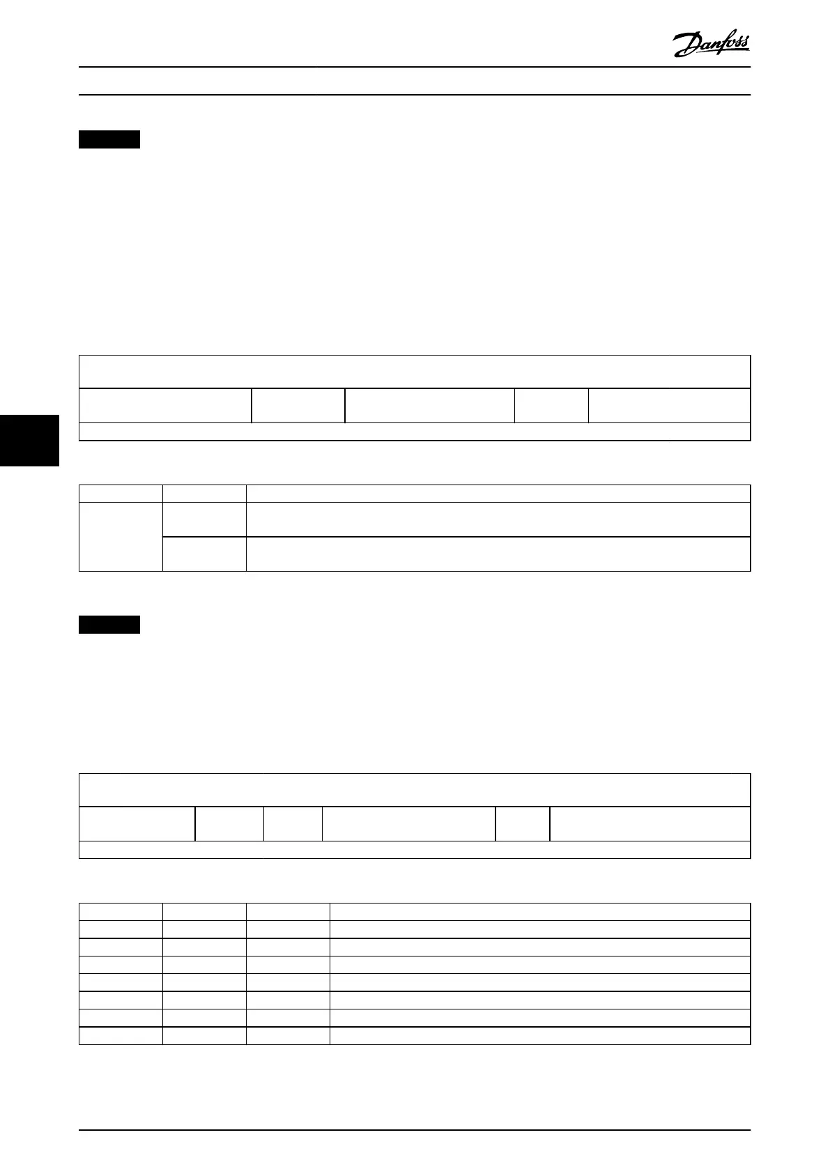
7.3.1.3 Statusword in Prole Torque Mode
The Prole Torque mode uses some bits of the Statusword for operation mode-specic purposes. Table 7.30 shows the
structure of the Statusword. Table 7.31 denes the values for bit 10.
15
14 13 12 11 10 9 0
See Table 7.23. Reserved (0) See Table 7.23.
Target
reached
See Table 7.23.
MSB LSB
Table 7.30 Statusword in Prole Torque Mode
Bit Value Denition
10 0 Halt (bit 8 in Controlword) = 0: Target not reached.
Halt (bit 8 in Controlword) = 1: Axis decelerates.
1 Halt (bit 8 in Controlword) = 0: Target reached.
Halt (bit 8 in Controlword) = 1: Velocity of axis is 0.
Table 7.31 Denition of Bit 10
NOTICE
Bit 10: Refer to Target reached option code (see chapter 7.20.2 Parameter 50-42: Target Reached Option Code (0x2054)) to
inuence the behavior of this bit. Also refer to chapter 2.4.2 Prole Velocity Mode for the functional description.
7.3.1.4 Statusword in Homing Mode
The Homing mode uses some bits of the Statusword for operating mode-specic purpose. Table 7.32 shows the structure of
the Statusword. Table 7.33 denes the values for bits 10, 12, and 13.
15
14 13 12 11 10 9 0
See Table 7.23.
Homing
error
Homing
attained
See Table 7.23.
Target
reached
See Table 7.23.
MSB LSB
Table 7.32 Statusword in Homing Mode
Bit 13 Bit 12 Bit 10 Denition
0 0 0 Homing procedure is in progress.
0 0 1 Homing procedure is interrupted or not started.
0 1 0 Reserved.
0 1 1 Homing procedure is completed successfully.
1 0 0 Homing error occurred, velocity is not 0.
1 0 1 Homing error occurred, velocity is 0.
1 1 X Reserved.
Table 7.33 Denition of Bits 10, 12, and 13
Servo Drive Parameter Descr...
VLT
®
Integrated Servo Drive ISD
®
510 System
240 Danfoss A/S © 01/2017 All rights reserved. MG36D102
77

 Loading...


