NOTICE
The manufacturer-specic bit 8 of the Statusword is also inuenced by the homing mode. The bit is set if the homing
procedure was successful. This bit remains set until the servo drive is power-cycled, reset, a position overow occurred,
or a new homing procedure is started. The bit is reset when the encoder oset mode has been used because this
functionality can also inuence the position.
The manufacturer-specic bit 15 of the Statusword is also used by the homing mode. The bit is set if a homing
procedure is started but the conguration does not allow it (for example, limit switch is not congured when trying to
do a homing on limit switch).
7.3.1.5 Statusword in CAM Mode
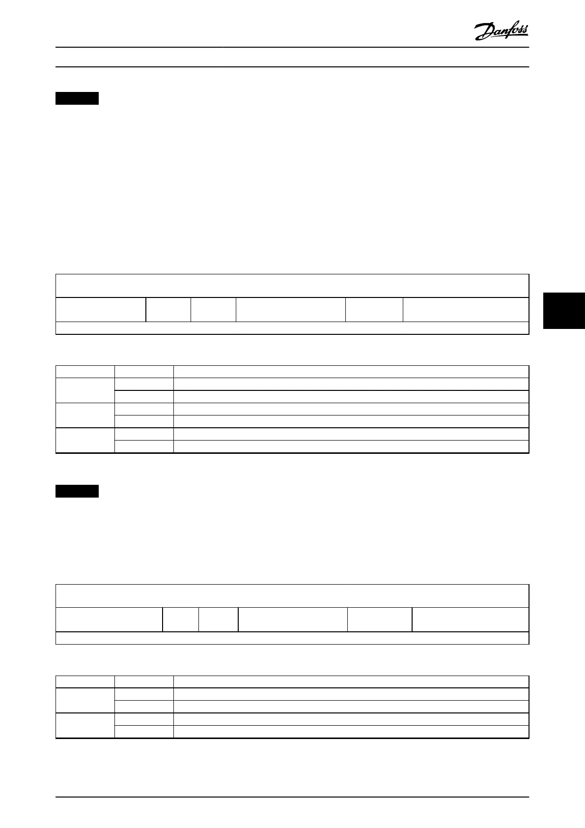
The CAM mode uses some bits of the Statusword for operation mode-specic purposes. Table 7.34 shows the structure of the
Statusword. Table 7.35 denes the values for bits 10, 12, and 13. For more status information, see chapter 7.14.8 Parameter:
CAM Prole Status (0x3805).
15
14 13 12 11 10 9 0
See Table 7.23.
Following
error
CAM ack See Table 7.23.
Target reached
(InSync)
See Table 7.23.
MSB LSB
Table 7.34 Statusword in CAM Mode
Bit Value Denition
10 0 Axis is blending. Current position is automatically calculated by the CAM.
1 Setpoints of the CAM are processed.
12 0 Previous CAM prole already processed, waiting for new CAM prole.
1 Previous CAM prole still in progress, new CAM prole will be accepted.
13 0 No following error.
1 Following error.
Table 7.35 Denition of Bits 10, 12, and 13
NOTICE
Bit 13: Refer to chapter 2.7.3 Following Error Detection for more information about the following error detection.
7.3.1.6 Statusword in Gear Mode
The Gear mode uses some bits of the Statusword for operation mode-specic purposes. Table 7.36 shows the structure of the
Statusword. Table 7.37 denes the values for bits 10, 12, and 13.
15
14 13 12 11 10 9 0
See Table 7.23
Followin
g error
Sync
started
See Table 7.23
Target reached
(InSync)
See Table 7.23
MSB LSB
Table 7.36 Statusword in Gear Mode
Bit Value Denition
10 0 Axis is not (yet) in sync with the given guide value.
1 Axis is in sync with the given guide value.
12 0 Not in synchronization movement (either not started or already in sync).
1 In synchronization movement.
Servo Drive Parameter Descr... Programming Guide
MG36D102 Danfoss A/S © 01/2017 All rights reserved. 241
7 7

 Loading...


