9 Diagnostics
9.1 System Monitoring
A warning or an alarm is signaled by the relevant indicator
light on the device and indicated by an error code. If faults
occur during servo system operation, check:
•
The LEDs on the servo drive for general problems
relating to communication or device status.
•
The LEDs on the SAB for general problems with
communication, auxiliary supply, or STO voltage.
The error codes can be read using the ISD Toolbox
software, the LCP, or the PLC. The LCP only shows faults
relating to the device it is connected to.
A warning remains active until its cause is no longer
present, however the operation of the device may still be
continued. Warning messages may be critical, but are not
necessarily so. In the event of an alarm, the device goes to
Fault state.
Reset the alarm to resume operation. Reset alarms that are
not trip-locked using 1 of these 3 methods:
•
Using the [Reset] key on the LCP.
•
Using the PLC function block MC_Reset_ISD51x or
DD_Reset_SAB.
•
Using the ISD Toolbox.
If an alarm cannot be reset, the reason may be that the
cause has not been
rectied, or the alarm is trip-locked
(see Table 9.2) and (Table 9.5).
Alarms that are trip-locked
oer extra protection, meaning
that the supply voltage must be switched o before the
alarm can be reset. After being switched back on, the
device is no longer blocked and can be operated normally.
Use Wireshark
®
if there are network problems. Wireshark
®
is a free and open-source packet analyzer. It is used for
network troubleshooting, analysis, and software and
communications protocol development. It can be
downloaded via the Wireshark
®
webpage (wireshark.org).
NOTICE
If the fault cannot be eliminated by 1 of the measures
listed in Table 9.1 or Table 9.4, notify Danfoss Service.
Have the following information available to enable Danfoss
to provide help quickly and eectively:
•
Type number
•
Error code
•
Firmware version
•
System set-up (for example, number of servo
drives and lines).
9.2 Drive
9.2.1 Troubleshooting
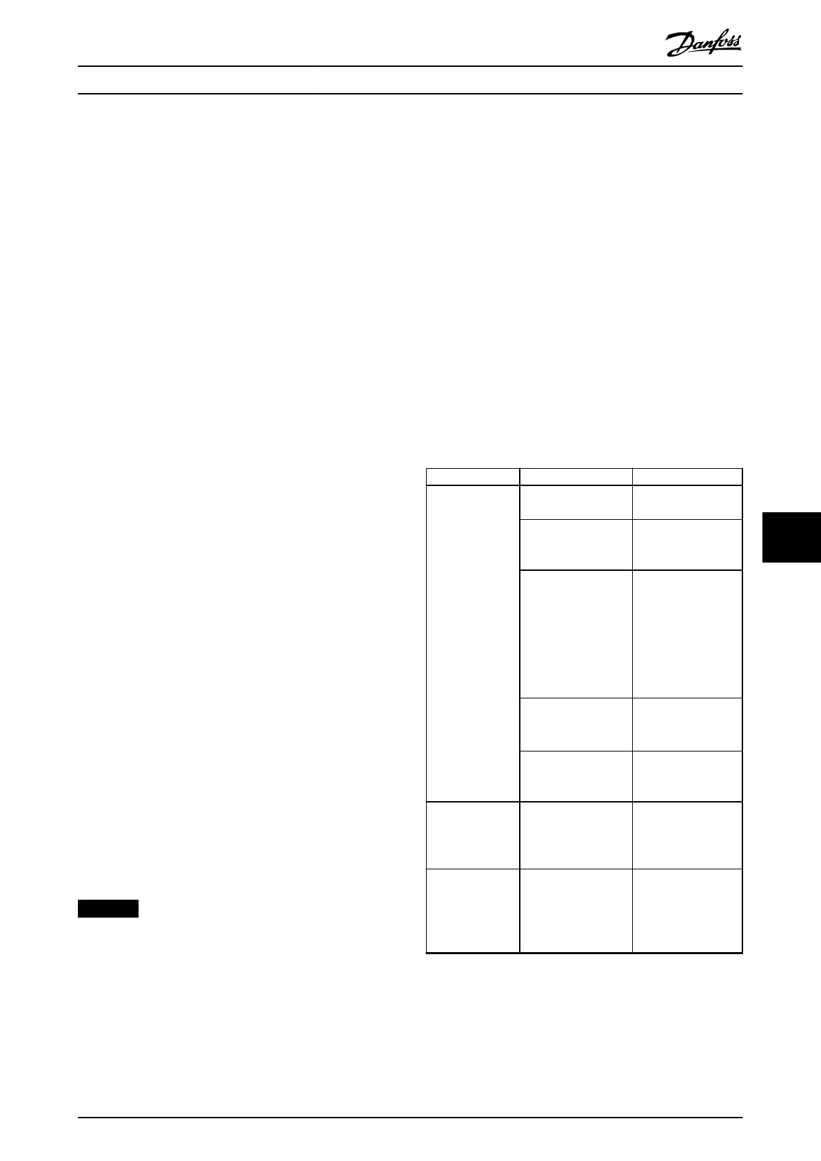
First use Table 9.1 to check the possible causes of the fault
and possible solutions. The error codes are listed in
chapter 9.2.2 Error Codes.
Fault Possible cause Possible solution
LCP display dark
or has no
function.
Missing input power. Check the input
power source.
Missing or open fuses
or circuit breaker
tripped.
Check the fuses and
circuit breaker.
No power to the LCP.
•
Check the LCP
cable for proper
connection or
damage.
•
Replace any faulty
LCP or connection
cables.
Incorrect contrast
setting.
Press [Status] +
[
▲
]/[
▼
] to adjust the
contrast.
Display is defective. Replace the faulty
LCP or connection
cable.
Servo drive
overheats (high
surface
temperature).
Excessive load. Check the torques.
Servo drive not
running.
No drive communi-
cation or drive in
error mode.
Check the eldbus
connection and the
status indicators
(LEDs) on the servo
drive.
Diagnostics Programming Guide
MG36D102 Danfoss A/S © 01/2017 All rights reserved. 367
9 9

 Loading...


